Table of Contents
Introduction
Scope
The final goal of this application note will be to gateway a signal through the Com module in the application ECU. The signal will be sent from the Test ECU through the Application ECU to a Target ECU as show in the diagram below:

You will be shown how to add a signal to an existing ECU and configure it to be gatewayed through the Com module so that the data transmitted is exactly the same as the data that is received. The route that the PDUs will take will look like:

This application note will create this implementation.
It should be noted that there is an alternative method of implementing the gatewaying of signals where all PDUs are routed as follows:

This application note will NOT create this implementation.
We will not be using this method in this guide as we don't want do gateway every signal in the Application ECU. There will be a separate application note made on how to do this.
We will cover the generation of the BSW, RTE, OS from RTA-CAR and the VRTA MCAL to support this. Most of the creation of the configuration will be automatically handled by the DBC importer and the BSW configuration generator, however there are some steps that are involved in changing your initial DBC, adding a second network and the configuration to support this, and defining how the signal is gatewayed in Com. The process itself is quite short and should be able to be covered by someone familiar with the prerequisite tools in a couple of hours.
Some of the steps involved with this process is only related to the fact that a second network is being added during this process. It will be made very clear when a step is only for adding the second network and not for configuring the signals and their gateway.
By the end of the guide you should be able to use a tool such as BUSMASTER to observe the PDU being passed through the ECU correctly with no interaction with ASW.
Definitions and Abbreviations
BSW: AUTOSAR Basic Software, Hardware independent service layer
RTE: AUTOSAR Run-Time Environment
OS: AUTOSAR Operating System
SWC: Software Component
CAN: Controlled Area Network
ECU: Engine/Electronic Control Unit
SK: Starter Kit
DBC: DataBase for Can
Gw: GateWay
SR: Sender-Receiver
IF: InterFace
Confgen: Configuration Generation
Toolchain
It is assumed you are using the RTA-CAR 9.2.0 toolchain:
RTA-CAR 9.2.0 toolchain | |
|---|---|
| ISOLAR-AB | v 9.2.0 |
| RTA-RTE | v 7.5.0 |
| RTA-BSW | v 6.1.2 |
| RTA-OS | v 6.2.0 |
Prerequisites
In order to successfully follow this guide, you must have the RTA-CAR toolchain installed, and you must be familiar with the AUTOSAR specifications, terminology and methodology.
The steps described in this guide will be performed on the 9.2.0 Standard VRTA starter kit. It is recommended that for the first time that you follow these steps you also complete them on the 9.2.0 Standard VRTA starter kit.
To test the changes we have made you may also want to have BUSMASTER and the BOA loopbackserver installed.
Workflow Summary
- Edit and import DBC
- Update ASW
- Create BSW configuration and code
- Generate RTE
- Generate OS
- Create MCAL
- Build and test
Step 1. Edit and import DBC
1.1 Add Gw Tx signal to existing DBC
We will first add the signal TestEcu_SG_Gw_Tx to the existing network and controller. This will be the signal that is sent from the Test ECU and received by the Application ECU.
Add the below lines to the file "System.dbc" at VRTA_GCC_Standard\Implementation\RTA-SK\system_config\:
BO_ 6 TestECU_Gw_Tx: 8 TestECU
 SG_ TestECU_SG_Gw_Tx : 0|8@1- (1,0) [0|0] ""  ApplicationECU
For example:

Then re-import the file "System.dbc":

There is a an option to import the new signal as a gateway signal or a COM signal. For this guide we will be using the COM signal option, this will make it easier to create BSW configuration

1.2 Define new DBC describing second network
Now we will configure the second signal, carrying the data after the signal has been gatewayed through Com. This will be our ApplicationEcu_SG_Gw_Tx which will come from the Application ECU and be sent to the Target ECU. Create a new file under the directory VRTA_GCC_Standard\Implementation\RTA-SK\system_config\ and name it something like "SystemGwTargetNetwork.dbc" - anything to make it obvious this describes the new CAN network you are adding to the project. Add a definition for the new signal e.g. the new lines below. Note the change in the ECUs used:
BU_: ApplicationECU TargetECU

BO_ 7 ApplicationECU_Gw_Tx: 8 ApplicationECU
 SG_ ApplicationECU_SG_Gw_Tx : 0|8@1- (1,0) [0|0] "" TargetECU
For example:

Then import the new DBC into the same file and package as the last DBC but into a new CAN network with a new CAN controller.

There is a an option to import the new signal as a gateway signal or a COM signal. For this guide we will be using the COM signal option, this will make it easier to create BSW configuration

Step 2. Update ASW
2.1 Create SR_IF
Create a primitive application data type and map it to a uint8 in an existing data mapping set.


Create a new sender-receiver interface with a new variable data prototype. Call the sender-receiver interface SR_Gw_uint8 and add to the existing System package in "interfaces.arxml" in the VRTA_GCC_Standard\Implementation\RTA-SK\system_config\ directory.


2.2 Edit MasterSWC
MasterSWC represents the software component that is contained within the ApplicationECU, we will add the definitions for ApplicationECU to recieve the TestEcu_SG_Gw_Tx signal and to send the ApplicationEcu_SG_Gw_Tx signal.

Add the receiving (RPort) and providing ports (PPorts) to the MasterSWC using the type SR_Gw_uint8.


Give the RunnabaleEntity RE_RunTest the data access points, DataSendPoints and DataReceivePointsByArguments for the newly added ports.

2.3 Edit TesterSWC
TesterSWC represents the software component that is contained within the TestECU, we will add the definition for TestECU to send the TestEcu_SG_Gw_Tx signal.

Add the providing port (PPort) to the TesterSWC using the type SR_Gw_uint8 in the same manner as you did for the MasterSWC.
Give the RunnabaleEntity RE_Tester the data access point DataSendPoints for the newly added port in the same manner as you did for the MasterSWC.
2.4 Create TargetSWC
Currently in the starter kit there is no SWC such as "TargetSWC". We will have to add a new SWC called TargetSWC and give it the objects and definitions it requires to receive the ApplicationEcu_SG_Gw_Tx signal.

Create a new SWC and name it TargetSWC, then create an internal behavior as its child and open the TargetSWC with the Component Editor


Create a new receiving port of the type SR_Gw_uint8 in the same manner as you did for the MasterSWC.
Create a new Runnable Entity and add access point DataReceivePointsByArguments.

Add a new timing event with a period of 0.01 seconds.


2.5 Update composition component prototypes and connections
Currently we have created the definitions for 3 SWCs that describe the data in and out of out ECUs but not the data between them:
To connect these SWCs we must open the TopLevelComposition:

Then add the Component Prototype "CPT_TargetSWC":


Then, open the Manual Connection Editor and connect the transmitting port on the CPT_TestSWC to the receiving port CPT_MasterSWC.

Connect the transmitting port on the CPT_MasterSWC to the receiving port CPT_TargetSWC.

Now when you open the TopLevelComposition in the Composition Overview you can see the structure of the SWCs reflect the diagram we had at the start:

You can see the CPT_TesterSWC connects to the CPT_MasterSWC which connects to the CPT_TargetSWC and has the ports on each side of each SWC:

2.6 Map signals to ports
We have the ports to transmit and recieve the signals; we must map the signals to their ports on the ApplicationEcu.
First open the System Data Mapping Editor:

Then drag the signals from the Avaliable Signals box on the right to the desired ports on the left:
- Map TestECU_SG_Gw_Tx to the receiving port you created on the MasterSCW.
- Map ApplicationECU_SG_Gw_Tx to the providing port you created on the MasterSCW.


2.7 Generate ECU Extract
Finally, regenerate the ECU Extract:


You may experience an warning such as "System version is not specified, default System version will be added to the extracted System". This is okay and can be ignored.
Step 3. Create BSW configuration and code
3.1 Run Confgen
Generate the ECU configuration to get the the conifiguration the new signals added.


3.2 Add GwMapping
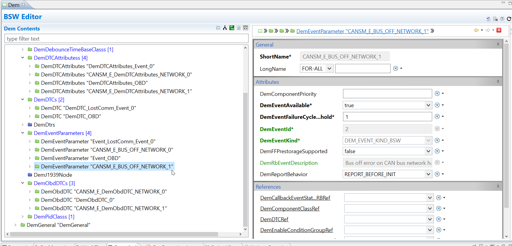
Open the Com module in the BSW editor

Split the view of the module, we want to create some static configuration; if we were to create the GwMapping in the file generated by ConfGen there is a chance in future executions of ConfGen the static configuration will be lost.

Create a new child "ComGwMapping" under the ComConfig in the file Project_EcucValues_UserConfig.arxml (or any other sensible static configuation file)

Map the signal TestECU_SG_Gw_Tx to the source signal and the signal ApplicationECU_SG_Gw_Tx to the destination signal:

3.3 Add Config for second network
These steps are only for configuring a second network. It is required during this process of modifying the starter kit, but independent of the gateway configuration.
Add the 4 containers for "NETWORK_1" as shown in the screen shots below.
The parameter names highlighted in green are generated during code generation and cannot be changed by the user.


Now in the BswM module you need to add two actions to the rule BswM_AR_StartCom. The first must be of type BswMComMAllowCom and the second BswMComMModeSwitch.
The Index of these actions must be higher than that of the action BswM_Al_BswMSWitchAppRun.

Open the actions in the BSW editor for the BswM module and set the ComAllowed value to true and the channel ref as the new networks channel produced by confgen:

Similarly, set the Requested Mode value to BSWM_FULL_COM and the channel ref as the new networks channel produced by confgen:

3.4 VRTA MCAL limitations
If you are following this application note with the Standard VRTA starter kit as suggested, then you may require to implement the following workarounds to suit the limitations of the VRTA MCAL:
- You may need to add a HwFilter to the Tx Mailbox created for your new signal being transmitted on the new network.
- You may need to create a receiving hardware object for your new controller for your second mailbox. (This is because a controller must have at least one transmitting and one receiving hardware object in the VRTA MCAL)

3.5 Generate BSW code

Step 4. Generate RTE
4.1 Map new runnables
Open the EcucValueCollection in the RTE Mapping Editor and select the tab at the bottom of the window for Entity To Task Mapping.

Click and drag the entity SE_GwMainFunction into the OsTask_BSW task:

Do the same for the main function for the new Can network channel into the same OsTask_BSW task:

4.2 Generate RTE code

Step 5. Generate OS
5.1 Generate OS code

Step 6. Create MCAL
6.1 Configure your MCAL
You may need to make changes to your MCAL configuration to support the new HW objects added for the second network such as the new controller or its mailboxes. For example the VRTA MCAL requires you to update the configuration file "Vecu_BoaWinCan_EcucValues.arxml" to give it a definition for the second network:

6.2 Generate MCAL
Run the script that generates your MCAL e.g. 01_mcal.bat in the Build folder of the starter kit.


Step 7. Build executable
Run the script that builds your executable e.g. 02_build.bat in the Build folder of the starter kit.

Running the VECU
When running the BOA VECU with two networks you must specify which controllers will be used my the controller to communicate. To do this you can simply add the below text in a file called BOA_Device_list.txt.
allow *ETH/ES523:VLoopBack/CAN:1
allow *ETH/ES523:VLoopBack/CAN:2
Then place this text file next to the executable before running it:

Testing Gateway Functionality with BUSMASTER
If you are following this application note with the Standard VRTA starter kit as suggested, then you may require to change the virtual OCD file that your BOA uses; edit the VirtualOcd.xml file in your serverOCDs folder in your BOA installation location to have references to at least 2 different CAN busses accross all of the controllers you are using:

You should now be able to test the functionality in BUSMASTER. You can do this by setting up one instance of BUSMASTER on the first bus to act as the TestECU and another instance of BUSMASTER on the second bus to act as the TargetECU.
When you send data from the TestECU with the CanID of your TestECU_Gw_Tx Frame using the TestECU instace your other instance should recieve the exact same data but with the CanID of your ApplicationECU_Gw_Tx Frame.
