LIN
PDU Router
The LIN Interface connects to the PDU Router and/or alternative modules above (e.g. Complex Driver) for transmission and reception of frames. It is assumed that these modules are responsible for the copying of the data of the frames for reception and transmission. In case of TP, the PDU Router is the only module above and handles the TP messages buffers either as complete or fragmented messages.
LIN State Manager
The LIN Interface connects to the LIN state manager which is responsible for the control flow of the whole LIN stack. Therefore, it has the following purposes regarding the LIN Interface:
- For master nodes, the state manager forwards a schedule table request to the LIN Interface.
- The state manager requests the transmission of the wake-up and, for master nodes, the sleep command.
BswM
LIN TP that is a part of LIN Interface connects to BswM for requesting the schedule table change when upper layer requests the LIN TP operation.
COM
The LIN Interface used as LIN slave connects to the COM to update the value of the response_error signal.
LINIF
The LIN Interface shall support the behavior of master and slave
LIN Driver
The LIN Interface does not use or access the LIN hardware or assume information about it any way other than what the LIN Driver provides through the function calls to the LIN Driver

Main Properties
- single master with multiple slaves concept
- low cost silicon implementation based on common UART/SCI interface hardware, an equivalent in software or as pure state machine.
- self synchronization without a quartz or ceramics resonator in the slave nodes
- deterministic signal transmission with signal propagation time computable in advance
- low cost single-wire implementation
- speed up to 20 kbit/s.
- signal based application interaction
- predictable behavior
- reconfigurability
- transport layer and diagnostic support
LIN vs CAN
- LIN is lower cost (less harness, no license fee, cheap nodes)
- CAN uses twisted shielded dual wires 5V vs LIN single wire 12V
- A LIN master typically serves as gateway to the CAN bus
- LIN is deterministic, not event driven (i.e. no bus arbitration)
- LIN clusters have a single master - CAN can have multiple
- CAN uses 11 or 29 bit identifiers vs 6 bit identifiers in LIN
- CAN offers up to 1 Mbit/s vs. LIN at max 20 kbit/s

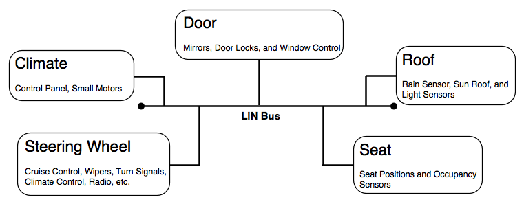
LIN nodes are typically bundled in clusters, each with a master that interfaces with the backbone CAN bus.
Example: In a car's right seat you can roll down the left seat window. To do so, you press a button to send a message via one LIN cluster to another LIN cluster via the CAN bus. This triggers the second LIN cluster to roll down the left seat window.
Work Flow
The Configuration Language Specification allows for safe sub-contracting of nodes without jeopardizing the LIN system functionality by e.g. message incompatibility or network overload. It is also a powerful tool for debugging of a LIN cluster, including emulation of non-finished nodes.
The Node Capability Language Specification, provides a standardized syntax for specification of off-the-shelves slave nodes. This will simplify procurement of standard slave nodes as well as provide possibilities for tools that automate cluster generation. Thus, true Plug-and-Play with slave nodes in a cluster will become a reality.
The slave nodes are connected to the master node forming a LIN cluster.
The corresponding node capability files are parsed by the LIN cluster design tool to generate a LIN description file (LDF) in the LIN cluster design process.
The LDF is parsed by the LIN cluster generator to automatically generate LIN related functions in the desired nodes (the Master node and Slave3 node in the example shown in the picture above).
The LDF is also used by a LIN bus analyzer/emulator tool to allow for cluster debugging.

Node

Master and slave

Data transport
- Signals: scalar values or byte arrays that are packed into the data field of a frame. A signal is always present at the same position of the data field for all frames with the same frame identifier.
- Diagnostic message: transported in frames with two reserved frame identifiers. The interpretation of the data field depends on the data field itself as well as the state of the communicating nodes.
Frames

Schedule table
The master task (in the master node) transmits headers based on a schedule table. The schedule table specifies the frames and the interval between the start of a frame and the start of the following frame. The master application may use different schedule tables and select among them.
LNM
- Collection of all: input signals, input integrity signals and all conditional logic related to switch the LIN Schedules
- Execute the logic to switch the LIN Schedules
- Enable the LIN Network when enabled by SUM_SUSD
- Put the LIN Network to sleep and notify SUM_SUSD
- Detect U codes for Node Loss detection to SUM_SSFM-ERRH
- Support Diagnostics of Functional Capability (B Codes, P Codes)
- Interface with DCM to receive: any required DID requests relevant to the MSCL, any required RID requests relevant to switching the LIN schedules
- Calibration Download
- Responder Requested Wakeup Handling
- MSCL Information: Determine nodes on the bus.
- NAD Reconfiguration
SUM_LNMs Interfaces
- SUSD
- LNM receives Permit Excution
- LNM sends Shutdowm Permission
- SSFM-SSM
- LNM receives a signal integrity notification, the node timeout status
- LNM sends which LIN Responders are expected for the vehicle as configured
- SSFM-ERRH
- LNM indicates DTCs related to LIN U-Codes / B-Codes
- SWCs
- LNM receives signals from other local SW-C which are relevant to the logic to switch the LIN Schedules.
- LNM receives signals from other local SW-C which are relevant to the logic to acti/deactivate the LIN networks
- Calibration
- LNM receives the corresponding Responder’s availability value used for establishing the MSCL value.
- DCM
- LNM requests For any DIDs or RIDs relevant to changing LIN Schedules
- $F1BE to load the calibratable MSCL table
- BswM
- LNM provides of the current LIN Schedule for LIN Networks
- LNM request a Schedule Switch for LIN Networks
- LNM provides notification of the current status of LIN Networks
- LNM requests NoComm / FullComm for LIN Networks
- COM
- APINFO<x>


LIN Network Status (Start / Stop)
The LIN Network Status is controlled by SUM_LNM to enable the AUTOSAR BSW to be enable / disable the LIN Network API related to the LIN network.
- Start/stop LIN Network logic in SUM_LNM.
- Start Phase
- Init Phase
- Green Start vs. Normal Start
- Normal Cyclic Phase
- Single Pass Schedules
- Configuration Schedules
- NAD Reconfiguration Schedules
- Part Number Schedules
- Pre-Sleep Phase
- Sleep Phase
- Optional User Function Implementation

- Start Phase: illustrates the SUM_LNM state prior to initialization. SUM_LNM is not executing in this state.
- Enter Criteria: Power is applied to the ECU microcontroller and SUM_LNM is not initialized yet.
- Exit Criteria: SUM_LNM is initialized by BswM, and the Init state is entered.
- Init Phase: is entered when SUM_LNM is initialized by BswM. In this phase, SUM_LNM must initialize all its variables and states to their correct initial states. SUM_LNM shall remain in the Init phase until BswM notifies that FullComm is achieved on the LIN Network and the conditions allow a switch to a LIN schedule.
- Green Start vs. Normal Start: Some LIN Networks may require a project specific schedule called a “Green Schedule” if the LIN Network is not properly configured.
- Normal Cyclic Phase: switch to different LIN schedules that may be different Normal Cyclic schedules or Single Pass schedules. When those events expire or the schedule is completed, the LIN Schedule typically reverts to the Normal Cyclic schedule. This behavior continues until a project specific event occurs which requires the LIN Network to exit the Normal Cyclic phase and shut down to sleep.
Network Fault Manager Requirements
LIN Commander ECUs monitor and detect the following failures with LIN Responders:
- LIN Loss of Communication with Responder Device
- LIN Loss of Communication with Sub Bus
LIN Responder Device Internal Electronic Failure
LIN Responder Device Not Configured
LIN Responder Device Missing Calibration
LIN Responder Device Not Activated
Collector
- DID $F1BE Report MSCL
- Report Part Numbers for LIN Responders
- RID $023A On Vehicle Responder Node Configuration Request
- RID $023B Responder Node Part Number Acquisition Request
- RID $05FA Responder NAD Reconfiguration
SUM LNM shall implement a user function LNM_CheckEnableConditions, for SUM LNM to request the RID enable condition arbitration from separate software component by passing the RID $(number).
LinIf
These APINFO signals are received by the LinIf module and passed to the RTE via Com and can be added as receive ports by SUM_LNM.
[SUMLNM264] SUM_LNM shall remain in the Init phase until BswM notifies that FullComm is achieved on the LIN Network and the conditions as specified by SDV-5181 allow a switch to a LIN schedule.
RATIONALE: LINSM will not allow a LIN Schedule switch request to be requested to LINIf on a LIN Network that is not activ
Configuration Schedules
The SUM LNM is required to Tx the calibration data to COM, based on detail requirements, after the configuration LIN schedules are invoked.
The SUM LNM shall store the LIN TP Identifier [ID1, ID2] for each Responder requiring LIN TP method calibration download as calibration parameter LNM_LINTPID<n> based on the LIN TP ID1 and ID2 values.
LNM_LINTPID<n>: N instances of this parameter are needed, 1 for each of N LIN Responders which have a LIN TP method calibration file stored in LIN Commander memory. This parameter represents the unique identifiers LINTP ID1 and ID2 used in LIN TP method calibration download communication. The LIN TP ID1 and ID2 values are listed in SDV-5181 for each LIN responder N using LIN TP method calibration download.


NAD Reconfiguration
Some ECUs may have project specific NAD Reconfiguration LIN schedules in SDV-5181. If such schedules exist, then the NAD Reconfiguration tables will be implemented within SUM_LNM.The logic to buffer and transmit the NAD Reconfiguration signal(s) will be contained within the Lin Interface, which will use the LinIfFixedFrameSduByte container to store the transmit data, but SUM LNM will control the NAD Reconfiguration schedule transitions using the LNM_BswM_ LinSM_ScheduleRequest<n> interface. The following requirements apply to LIN Commander ECUs that use in-vehicle NAD Reconfiguration of LIN responders.
LinIfFixedFrameSduByte
LinIfChannel → LinIfFrame → LinIfFixedFrameSdu → LinIfFixedFrameSduByte → LinIfFixedFrameSduByteVal
→ LinIfFixedFrameSduBytePos
When the 0x3C request frames use fixed data values, which is the case for the 0x3C NAD Reconfiguration frames, then these data values may be stored in the Lin Interface configuration LinIfFixedFrameSduByte without the need to store this data in an upper layer software component configuration as required with LIN TP.
Furthermore, for each 0x3D positive response that follows a Node Configuration fixed frame 0x3C request, then per Autosar, the Lin Interface is required to take no action with this received data, meaning to not forward the data to the upper layer as done using LIN TP.
However, given that SUM LNM is required to know whether a positive or negative response (including no response) is provided for each 0x3D response during NAD Reconfiguration schedules as part of its NAD Reconfiguration schedule transition arbitration and its RID 05FA test pass/fail criteria, a need to use callback LNM_LinIf_NADReconfiguration_End_Of_ST_Result<n> for Lin Interface to notify SUM LNM was required.