Used tool-chain | |
| ISOLAR-AB | v 4.0.2 |
| RTA-BSW | v 3.1.0 |
| RTA-RTE | v 6.5.0 |
| RTA-OS | v 5.5.11 |
| BUSMASTER | v 3.2.2 |
Introduction
Scope
This application note (AN) describes how to configure RTA-BSW to support the OBD protocol. The steps indicated in this AN are related to the sample project provided. The sample project implements the features described in the AN and can be used by the user as a reference.
Note: The scope of the AN is restricted to the configuration of the Diagnostic Modules (Dcm and Dem) for the OBD support. The configuration of the Communication Stack for the OBD messages is outside the scope of the AN. The assumptions on the needed configuration are briefly described in the following sections.
Assumptions
In this section all the assumption and prerequisites needed for the AN are collected.
Tools
You have familiarities with AUTOSAR Toolchain and you have the following ETAS software installed:
- ISOLAR-AB v4.0.2
- RTA-BSW 3.1
- RTA-RTE 6.5.0
- RTA-OS 5.5.11
- RTA-OS (Port) Tricore-HighTec v5.0.16
- Busmaster 3.2.2
None ETAS software:
- Infineon MCAL tc26x v400
- Python 2.7
- Hightec v4.6.5.0 or higher
- Tresos 16.0
- Scons 2.3.6
Sample project assumptions
The Sample Project provided together with this AN is based on the RTA-SK TC264 with RTA-BSW 3.1.
This AN is focused in the configuration of the Diagnostic Modules (Dcm and Dem) for OBD support. It is assumed to already have the Com stack configured as detailed in this section.
OBD General requirements
As defined in the OBD standard, the messages have a standard 11-bit identifier to distinguish between request messages (from the tester, with ID 0x7DF) and response messages (ID 0x7E8 to 0x7EF). In this example the ECU will have the ID 0x7E8 associated. Note that 0x7E8 is typically associated to the main ECU (MASTER ECU).
How to import OBD configuration
Supposing you are starting the OBD configuration from an ETAS Starter-Kit, you should already have the BSW configured for UDS communication.
You can then import the information on the OBD configuration form a dbc file. For this example, the dbc file provided with the ETAS SK has been modified adding the OBD signals information, as follows:

In order to follow the OBD specification, as explained above, two signals have been added:
- OBD Rx signal with Can ID 0x7DF
- OBD Tx Signal with Can ID 0x7E8
Once the dbc is updated with the new OBD frames, in order to update the System Template and the BSW configuration you should:
- Import the new dbc file and use the ISOLAR-A dbc merge view to ensure that the new frames are imported and the previous configuration is not overwritten.
- Use the split parameter function of ISOLAR-B in order to separate the parameters that may be overwritten running the confgen
- Run the confgen and verify that the OBD PDUs are created and the UDS PDUs are not overwritten/renamed
OBD requirements for COM
In order to support OBD, the Communication Stack shall be configured in the following way:
- 1 Can Rx Frame with ID 0x7DF (this frame shall be a functional CAN frame)
- 1 Can Tx Frame with ID between 0x7E8 to 0x7EF
- Can Tp configured to support 11 bits normal addressing
- Two separated frames for UDS and OBD
After you followed the steps in previous sections you should have the following OBD relevant
PDUs in your configuration:

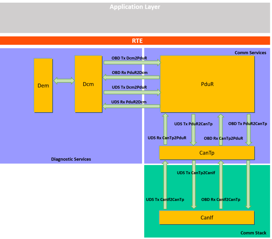
To give more context, please notice that the name of the PDUs contains information on where the PDU is used. For example, if the name of the PDU is “Diag_OBD_ON_CAN_Tx_Can_Network_CANNODE_0_Phys_CanTp2CanIf”, this indicates that one is an OBD Tx Pdu which comes from CanTp and goes to CanIf.
The following picture clarifies the path of the OBD and UDS PDUs:
General Dem Configuration
The objective of this chapter is to provide an overview to the basic Dem Configuration needed to support OBD.
In this chapter we are going to show how to:
- Updated the Dem General configuration for OBD support
- Configure the OBD mandatory Operational Cycles
- Add a new indicator and configure the MIL indicator (OBD mandatory)
- Update the NVM configuration for OBD
Note: The Dem configuration presented in this chapter is mandatory if you want to set the Dem in order to support OBD, regardless of the OBD services that are configured in Dcm.
Enable Dem OBD Support
The Dem shall be set in order to support the ECU type you want to use. According to AUTOSAR specifications, there are three types of ECUs (MASTER, PRIMARY, SECONDARY).
In RTA-BSW v3.1, it is possible to configure the ECU as PRIMARY or SECONDARY. If you want to configure it as MASTER, you shall follow the indications of chapter , where further details are provided on how to extend the support to MASTER ECUs using RTA-BSW v3.1.
In this example the DemOBDSupport is set to DEMOBDPRIMARY_ECU.

Configure the DemGeneralOBD
Once the Dem is configured for OBD support, it is mandatory to configure the DemGeneralOBD container. You can configure it as follows:

Configure also the DemMaxNumberEventEntryPermanent to 4 (mandatory for OBD legislation).
![]()
In version RTA-BSW 3.1 the “Centralized handling” of PID $21 and PID $31 shall be set to “false” as shown in the previous screenshot. It is possible to implement the Centralized PID handling using the AUTOSAR strategy, see chapter 10 for further details.
Dem Operation Cycles
The Dem must be configured with the DemOperationCycles mandatories for OBD. The mandatory Operation Cycles are:
- DEM_OPCYC_WARMUP
- DEM_OPCY_IGNITION
- DEM_OPCY_OBD_DCY
Add the abovementioned Cycles, configuring for each of them the “DemOperationCycleType” field with the same name of the cycle itself.
The result of the configuration is shown below:

It is outside the scope of this Application Note to explain how to handle Operation Cycles using Dem.
Add a Dem OBD DTC
It is possible to add new OBD related DTCs to the Dem configuration. To do so, right click on “DemObdDTCs” container and click on “Create DemObdDTC”. You can then set the name of the created DTC. As result, you should have a configuration similar to the one shown in the screenshot below:

The DemObdDtc shown in the screenshot “CANSMEDemObdDTCNETWORK0” must be configured if the OBD support is enabled. It is now possible to relate a classic DemDTC to a DemObdDTC. As example, we created a new DemObdDTCs called “DemObdDTC_0” and we connected this OBD DTC to the already existing DTC “DemDTCLostComm_SEN”. An existing DTC has been used in this example, since the configuration of a DTC is outside of the scope of this AN.

If you configured a DTC as OBD related, the following proprieties shall be set in the DTC Attributes:


Another mandatory change is related to the Event connected to the DTC. The Event shall have as DemOperationalCycle the OBD specific Operation Cycle DEM_OPCY_OBD_DYC.

Note: In order to have the OBD relevant DTCs working, be sure that the Operational Cycles are correctly handled.
Set the MIL indicator
When you set the Dem to support OBD, it is mandatory to add a reference to the MIL Indicator. The first step is to add a generic indicator in the Dem. The indicators are presented as ”DemIndicators”. Right click on the “DemIndicators” container to create a new generic Indicator. Since the indicator will be related to MIL, in this example it has been called “MIL_Indicator”.

Then it is possible to configure the reference to the MIL indicator in the Dem configuration. The DemMILIndicatorRef is into the container “DemGeneral”. Add the reference to the Indicator that has just been created.

Configure the Clear DTCs support
When OBD is supported, the Dem must be configured for “Only Clear” all DTCs options. This configuration is into the container “DemGeneral”.

This setting is mandatory when you enable the Dem to support OBD. In particular it is exploited for OBD Mode $04 (Clear DTCs).
Configure NVM for OBD
Configuring Dem for OBD, it is mandatory to have four memory location reserved for OBD permanent memory. Open the NVM configuration and add a new “NvMBlockDescriptor”. In the example the name chosen for the new block is “NvMBlockDescriptor_Dem_ObdMemory”.
The configuration used for the new NvMBlockDescriptor is reported in the following screenshots.


Now you can configure the Dem to reference to the created NvMBlockDescriptor. Add a new parameter under “DemNvRamBlockIds” and configure it as follows:


Note: Once you configured the Dem for OBD, you probably will need to update the size of the Dem NvM Blocks. The NvMNvBlockLength parameter shall be updated in all the already present DemNvRamBlockIds. This update is needed since in the Dem_Cfg_AssertionChk.h file some compile time checks are performed on Dem variables and types size. For example, if you open the file Dem_EvMemTypes.h and have a look to the Dem_EvMemEventMemoryType, you can see that the typedef depends on the Dem configuration. In particular, if you configure OBD, there are fields such as “ObdFFTimeId” that are added to the typedef:

Therefore, also the other DemNvramBlockIds shall be updated according. In our example, the NV block data length has been changed from 20 to 24 bytes.
RTA-BSW Codegen configuration
Once you configured also the Dem for OBD support, the run configuration of RTA-BSW codegen must be changed in order to generate the code of an OBD software library which contains callouts and code used by Dem. The name of this library is “Rba_DemObdBasic”. In order to change the codegen configuration, open the “Run Configuration” as shown in the picture below:

Then select the project configuration you are currently using:

Finally tick the box “Rba_DemObdBasic” and press apply to save the changes before closing the window.

General Dcm Configuration
The objective of this chapter is to provide an overview to the basic Dcm Configuration needed to support OBD. In this chapter we are going to show how to create a dedicated OBD service table and how to configure the Dcm to support OBD protocol.
Create a new OBD Service Table
As first step you shall create a new Service Table dedicated to OBD, since the reference to the Service Table will be needed in the second step (creation of the Dcm Protocol Row).

Assign to the new container you created the name “DcmDsdServiceTable_OBD”. The DcmDsdServiceTable is the container where all the other OBD Services (also called Modes) will be configured. More details on the configuration of OBD modes are presented in the next chapters.
Create a new DcmDslProtocolRow
Now you can create a new “DcmDslProtocolRow” to the Dcm configuration. Open the Dcm Configuration in ISOLAR-B view and right click on “Create DcmDslProtocolRow” as shown in the picture below.

A brief description of the most important parameters in the ProtocolRow configuration:
- DcmDslProtocolID: Here you can specify which is the diagnostic protocol the Dcm shall refer to. There are different supported options, for this AN we are obviously interested to “DCM_OBD_ON_CAN”.
- DcmDslProtocolPriority: This parameter defines the priority of the protocol in case of preemption handling (e.g. in case of coexistence of UDS_ON_CAN and OBD_ON_CAN)
- DcmDslProtocolRxBufferRef: Reference to the Rx protocol buffer used.
- DcmDslProtocolSIDTable: Reference to the Service Table defined in section 3.1 5. DcmDslProtocolTxBufferRef: Reference to the Tx protocol buffer used.
Now you can configure the new Protocol Row as follow:

Now the basic configuration of the Dcm is completed and it is possible to proceed configuring every OBD Mode.
Configure OBD Mode $01
The purpose of this service is to allow access to current emission-related data values. The request for information includes parameter identification (PID) value that indicates to the on-board system the specific information requested. In this chapter, the steps needed to configure the Mode $01 are presented.
Dcm Configuration
In order to configure the Dcm to support OBD Mode $01, you shall add the Mode to the Service Table you have created as explained in the previous chapter. Then you can proceed configuring the PIDs. The steps are described in the following sections:
Create the service
Create a new DcmDsdService right clicking on “DcmDsdServices” under the container “DcmDsdServiceTable” created for OBD. The same step shall be repeated for every new mode that you want to configure.

Here a brief explanation on the most important DcmDsdService parameters:
- DcmDsdSidTabFnc: With this parameter, you can configure which Dcm function will be called when the request of the corresponding OBD Mode comes to the Dcm. This field can be filled with automatic values. Select empty text box of this parameter and then press Alt+Space: the default values for this parameter will be shown.
- DcmDsdSidTabServiceId: This parameter is the identifier of the service. In this case shall correspond to the OBD Mode you are configuring.
- DcmDsdSidTabSubfuncAvail: Using this parameter you can select if there is any Subfunction available for the Service you are configuring.
- DcmRbDsdSidTabSidInitFunction: Using this parameter you can select if the Service you are configuring has an initialization function. If no init function is foreseen for that service, you shall set this parameter to NULL_PTR.
For OBD Mode $01, you can find in the screenshot below the configuration example.

Configure the PID
Now you can proceed adding a new PID. In this example the PID $01 will be configured. Open the DcmDsp configuration in ISOLAR-B, right click on “DcmDspPids” and select “Create DcmDspPid”.

After you created the PID, you can proceed with the basic configuration of the PID as shown in the figure below. The following parameter are configured:
- DcmDspPidIdentifier: This identifier shall correspond to the PID number. This means that PID $01 shall have this field configured to 1.
- DcmDspPidService: This parameter allows to select if the PID is used for Mode $01, Mode $02 or for both Mode $01 and $02.
- DcmDspPidSize: This parameter indicates the length of the PID in bytes. You can proceed configuring the PID as shown in the picture below.

Since the OBD Mode $02 has not been already configured, you can select DCM_SERVICE_01 for the DcmDspPidService configuration. Once you created the PID, you can configure the data associated to the PID itself, which will be returned when the ECU responds to the PID request coming from the tester. Create the new data right clicking on the DcmDspPidDatas container.

Complete the configuration as shown below:

The DcmDspPidDataSize and the DcmDspPidDataPos shall be consistent to the DcmDspPidSize previously configured. The DcmDspPidSize is the total size of the PID, counting the DcmDspPidDataSize and the DcmDspPidDataSupportInfo (if there are any configured). You can configure now the DcmDspPidService01 container. It contains the information about how the Dcm can retrieve the data related to the PID you are configuring. There are different solutions. It is possible to configure the Dcm in order to:
- Retrieve the PID value using a callback to the Application or implemented in the Integration code. In case the Dem computes the PID value, the shall be the reference to the interface that the Dem provides to the Dcm.
- Specify a Sender-Receiver port to the SW-C that will provide the value to the Dcm
- Specify a Client-Server port to the SW-C that will provide the value to the Dcm
The three possible parameter values are reported in the screenshot below:

In this example, the Mode $01 PID $01 is configured to retrieve the information from the callback “DcmAppl_DcmDspPidData_01”. The user shall create the abovementioned interface in the integration code. If a SR/CS interface is selected, the user shall create the interface in the Application SW. The following is the configuration used in the sample project.

Note: the same steps shall be repeated for every PID you want to configure.
PIDs computed by Dem
As mentioned before, for some of the PIDs the value is computed by the Dem. For this PIDs, the configuration steps of the Dcm is the same as the one shown in the previous section. The only difference will be the “DcmDspPidDataReadFnc”. This parameter shall be set to reference to the Dem interface to Dcm. According to AUTOSAR specification, the Dem interface to Dcm follows the nomenclature “Dem_DcmReadPID<NN>” where NN is the PID number.
Note: In RTA-BSW 3.1 the Dem does not support the computation of PIDs $21, $31, $4D, $4E, $91. Therefore the Dem interface to Dcm does not exist for these PIDs. More details on how to support these PIDs are provided in chapter 10.
Configure OBD Mode $02
The purpose of this service is to allow access to emission-related data values in a freeze frame. The request message includes a parameter identification (PID) value that indicates to the on-board system the specific information requested. In this chapter, the steps needed to configure the Mode $02 are presented.
Dem Configuration
In order to configure the Dem, it is needed to create a “DemPidClass”. In this example the PID configured is the PID $0D (which returns the Vehicle Speed).

Then it is needed to associate the PID to the “DemDataElementClass”.

Dcm Configuration
The configuration of OBD Mode $02 is similar to the configuration seen in chapter 4 for Mode $01. Configuring the Dcm, you shall create the service and add configuration for the supported PIDs.
Create the service
Refers to section 4.1.1 for detailed steps on how to create a new service. Once you created the Service for Mode $02, configure it as shown below:

Leave empty the configuration boxes not shown in the screenshot.
Configure the PID
The PID configuration started in section 5.1, shall be concluded connecting the PID configuration of the Dem to the PID configuration of the Dcm. Note: To use OBD Mode $02, the PID $02 is mandatory to be configured. The configuration of PID $02 shall be done in Dcm, but this PID shall not be referenced to a Dem PID. The reference between PID in Dcm and Dem must be done for all the other configured PIDs. In the example we configured the PID $0D, which contains the value of “Vehicle Speed”. In the Dcm configure the PID $0D as follow:

And the configuration can be concluded adding the reference to the Dem configuration as follow:

A new Dem Data Element Class has been created for OBD. You can create multiple classes according to the number of PID to be supported.

In this example we connected the Dem Data Element Class to the Vehicle Speed information.

Configure OBD Modes $03-07-0A
This diagnostic service provides the OBD DTCs. In particular:
- Mode $03: request “confirmed” DTCs
- Mode $07: request “pending” DTCs
- Mode $0A: request “permanent” DTCs
In this chapter, the steps needed to configure the Modes $03, $07 and $0A are presented.
Dcm Configuration
The Dcm configuration for the Mode $03/07/0A is the same as the other services. It is needed to add to the OBD Service Table these three Services. Each of the three service will be set to use the same routine “Dcm_DcmObdMode37A”, as shown in the screenshots below:


Dem Configuration
In order to use the OBD Modes described in this chapter, the Dem shall be configured to handle at least one OBD relevant DTC. How to configure DTCs is outside of the scope of this AN, but hints on the Dem configuration for OBD relevant DTCs are provided in chapter 2.
Configure OBD Mode $04
The purpose of this service is to provide a means for the external test equipment to command ECUs to clear all emission-related diagnostic information. In this chapter, the steps needed to configure the Mode $04 are presented.
Dcm Configuration
The configuration of OBD Mode $04 is similar to the configuration seen in chapter 4 for Mode $01. Configuring the Dcm, you shall create the service in the OBD Service Table.

Mode $04 callback and possible use cases
When the Mode $04 is triggered, a check is performed to verify if the conditions to clear the DTCs are fulfilled or not. Since these conditions are application specific, the Mode $04 provides a callback to the integration code where the logic to perform the check can be placed.

Note: There are additional usecases that can be addressed using the abovementioned callback. A possible usecase is to inform the ASW when the Mode $04 is executed. This information may be needed by the ASW in case of computation of some PIDs for Mode $01 or Mode $02.
Dem Configuration
The only mandatory Dem Configuration specific for Mode $4 is to set the “Clear DTC Support” as indicated in section 2.6.
Configure OBD Mode $06
The purpose of this service is to allow access to the results for On-Board Diagnostic monitoring tests of specific components/systems that are continuously and non-continuously monitored. In this chapter, the steps needed to configure the Mode $06 are presented.
Dcm Configuration
The configuration of OBD Mode $06 is similar to the configuration seen in chapter 4 for Mode $01. Configuring the Dcm, you shall create the service and add configuration for the supported OBDMID and create the reference to the supported TID.
Create the Service
Refers to section 4.1.1 for detailed steps on how to create a new service. Once you created the Service for Mode $06, configure it as shown below:

Leave empty the configuration boxes not shown in the screenshot.
Configure a new OBDMID
Once you created the Service for the Mode $06, you can configure the OBDMIDs and the related TIDs. Right click on the “DcmRbDspTestResultByObdmid” container and create a new “DcmRbDspTestResultObdmidTids” and a new “DcmRbDspTestResultTids”. Configure the OBDMID created setting the OBD test result ID. In the example the configured OBDMID is the one with ID 01:

Similarly to PID you can define the interface or callback the Dcm shall use to retrieve the information about the requested OBDMID. In the last field, you also have to set the reference to the corresponding TID.

The corresponding TID is set under the container “DcmRbDspTestResultTids” as follows:

Note: In RTA-BSW v3.1 OBD Mode $06 is not supported by Dem. It is possible to support the Mode $6 configuring the Dcm for retrieving the value of the requested OBDMID using using a callback or an interface to the ASW. To do so, you shall set the DcmRbDspTestResultObdmidGetDTRValueFnc to the correct value (i.e. to the name of the interface/callback to be used by the Dcm to request the value) and the DcmRbDspTestResultObdmidUsePort to the correct value (“true” if the value is requested through an interface to the ASW, “false” if it is requested through a callback to Integration Code).
Configure OBD Mode $09
The purpose of this service is to enable the external test equipment to request vehicle-specific vehicle information such as Vehicle Identification Number (VIN) and Calibration IDs. Some of this information may be required by regulations and some should be reported in a standard format if supported by the vehicle manufacturer. INFOTYPEs are defined in SAE J1979-DA. In this chapter, the steps needed to configure the Mode $09 are presented.
Configuring the Dcm
The configuration of OBD Mode $09 is similar to the configuration seen in chapter 4 for Mode $01. Configuring the Dcm, you shall create the service and add configuration for the supported Infotypes.
Create the Service
Refers to section 4.1.1 for detailed steps on how to create a new service. Once you created the Service for Mode $09, configure it as shown below:

Leave empty the configuration boxes not shown in the screenshot.
Configure a new InfoType
After the Service for Mode $09 has been created, you can add the configuration for all the Infotypes you want to support. In this example, Infotypes 0x01 and 0x22 have been configured. To create a new Infotype, right click on “DcmDspVehInfos” and then click on “Create DcmDspVehInfo”.

Set a ShortName for the created Infotype and set the DcmDspVehInfoInfoType to the correspondent value of the Infotype (the value shall be in decimal, e.g. for Infotype 0x22, set the value 34).

Inside the new container you just created, add a new DcmDspVehInfoData and configured as below:

You can set the callback used by the Dcm to retrieve the data associated to the configured Infotype using the parameter DcmDspVehInfoDataReadFnc. If the Dcm needs to use an interface provided by the Dem, you shall specify the name of this interface in this parameter.
Dem Configuration
The Dem basic configuration for OBD is the one reported in chapter 2. Some additional configuration for Mode $09 can be related to the IUMPR.
IUMPR configuration
In order to configure the IUMPR support, the DemRatio container must be configured with at least a new element. When you add a new DemRatio, you shall indicate which IUMPR group it belongs to and the group of the denominator. The DEM exposes the IUMPRDenominatorCondition interfaces for each of the four possible group. In the screenshot below, the exposed interfaces are shown.

It is requested that the ASW will provide the information requested by the Dem for the IUMPR Denominator Condition. The reason is that the Dem has not enough information to compute by its own the complex conditions requested to unlock/lock the increase of the IUMPR denominator. Using the mentioned interfaces, the lock/unlock of a particular denominator group can be handled by the ASW.
MASTER ECU support
In this chapter it is presented how to extend the support to the MASTER ECU. As mentioned before, the RTA-BSW v3.1 does not allow the Dem configuration to support MASTER ECUs, but it is possible to extend the support to the MASTER ECUs features anyway, following alternative configurations. Details on how to configure the BSW and the ASW strategies to use are provided in this chapter.
PIDs computed by the MASTER ECU
According to Dem AUTOSAR specifications, the following PIDs shall be computed by the Dem of the MASTER ECU:
- PID $21: “Distance traveled with malfunction indicator lamp (MIL) on”
- PID $31: “Distance traveled with malfunction indicator lamp (MIL) on”
- PID $4D: “Time run with MIL on”
- PID $4E: “Time since trouble codes cleared”.
- PID $91: “ECU OBD System Information”
In RTA-BSW 3.1 the Dem does not compute the values for the abovementioned PIDs, therefore the Dcm shall be configured to retrieve the information from the ASW or eventually from integration code callbacks.
Dcm configuration
It is possible to use a callback or specify a SW-C interface to provide the PID value to the DCM. Therefore, the PID value can be computed by the ASW or by Integration code callbacks. Let’s suppose to configure the PID $21 for Mode $01 that is normally reserved to MASTER ECU. The same procedure can be applied for the computation of PID $31, $4D, $4E, $91. The steps are the same as a described in section 4.1.2. Therefore, if you repeat the steps to create PID $21, in the PID configuration you can finally define from where the Dem will retrieve the value of the requested PID. At this point, you can define if the value of the PID $21 will come from a Port or an API placed in your integration code. According to your needs, you can configure the configuration parameters highlighted in the following screenshot:

Since PID $21, $31, $4D, $4E have a dependency on MIL status and DTC clear request, the ASW needs to know the status of the MIL and it needs to be notified when a request of Clear DTC has been approved (through OBD Mode $04 request by the tester). To retrieve the status of the MIL you can use the interface “Dem_GetIndicatorStatus” with the Indicator Id as parameter. In order to keep the SW-C aware of when the Clear DTC (OBD Mode $04) is executed, there is the possibility to fill out a callback in the integration code “DcmAppl_OBD_Mode04.c”. Inside the mentioned file, you will find a callback used for Mode $04 to check if the conditions to execute OBD Mode $04 are fulfilled.
You can fill the DcmAppl_OBD_Mode04 callback in order to notify the ASW of the executed clear DTC. The callback to the ASW shall be called only when all the other conditions on the execution of Mode $04 are fulfilled.
Centralized PID Handling Mode
The Centralized PID Handling Mode is the strategy that allows the MASTER ECU and the PRIMARY ECUs to synchronize in the foreseen for the PIDs which should be computed by Dem in the MASTER ECU. The synchronization procedure involves ASW, Dem and Dcm. Since in RTA-BSW v3.1 the Dem does not support the computation of PID $21, $31, $4D, $4E in the MASTER ECU, the “centralized PID handling mode” shall be handled only using Dcm and ASW.
Centralized PID Handling using Dcm and ASW
The centralized handling can be implemented excluding the Dem from the strategy and involving only Dcm and ASW. Supposing to configure PID $21, the steps are the following:
- Configure the Dcm to interface with a callback in the integration code or to a SW-C to retrieve the PID value
- Create a SW-C in the MASTER ECU which contains the logic to compute the PID $21 and send the value among the other PRIMARY ECUs.
- Create a SW-C in the PRIMARY ECU to receive the value of the PID sent by the MASTER ECU and memorize the value.
- The same SW-C in the PRIMARY ECU shall have an interface to Dcm in order to provide the value of the PID received from the MASTER when the OBD Mode $01 – PID $21 is requested from the tester.
Therefore, a PRIMARY ECU’s SW-C shall be foreseen to take the role of “synchronizer” with the MASTER ECU and the Dcm Module. How to configure the Dcm for Steps 1 and 4 is described in section 4.1.2.
Readiness Status
According to AUTOSAR Dem specifications [2]: “DemEventOBDReadinessGroup has a regulation background and special computations based on ModelYear (MY) and Market.” In order to ensure support different regulations and markets, the Readiness status will be handled by integration code and by the Application SW.
Interaction with ASW
The Dem module exposes the interface Dem_SetEventDisabled to the RTE. The SetEventDisabled does report an Event as “uncompletable” during the current driving cycle but it does not turn the Event into a Events Suppression. For the computation of PID $41, the monitor has to report its event as disabled, if the test cannot be carried out anymore until the end of this driving cycle. Let’s take as example the Oxygen Sensor Heater Monitor. When the ASW detects that the conditions to run this group of tests are not met, it can use the interface Dem_SetEventDisabled to disable that event. The Event will be considered as “uncompletable” and this can be reflected in the PID $41 value.
Integration code in RTA-BSW
As mentioned, since the Readiness Groups are dependent to regulations, Market and MY, the RTA-BSW provides the integration code to implement the computation of the PID $01 and PID $41 according to the requirements the OEM have to follow. The integration file that shall be changed to get this result is rba_DemObdBasic_Readiness.c.
Integration code for Dem_SetEventDisabled callback
The Dem_SetEventDisabled API implementation is in the file rba_DemObdBasic_Readiness.c and shall be filled by the user according to the Readiness Groups that are supported in the ECU. Inside the Dem_SetEventDisabled, the code shall check which is the Readiness Group of the EventId that has been passed as function argument. Once identified the Readiness Group associated to the EventId, the Readiness Group “status” can be updated and also the PID $41 value can reflect this status (e.g. the bit related to a monitor can be set as “disabled” or “enabled” for that monitoring cycle).
Integration code for PID $41 and PID $01
By default, the PIDs $41 and PID $01 return fixed values. Once the Dem_SetEventDisabled has been implemented, also the APIs: rba_DemObdBasic_Rdy_GetPid01ByteBCD rba_DemObdBasic_Rdy_GetPid41ByteBCD shall be updated with a new implementation. The values of bytes BCD for these PIDs needs to reflect the information received with the interface DemSetEventDisabled.
Testing the OBD
Once the Dcm and Dem are configured to support the OBD, it is possible to test the configured OBD services. As explained in the first chapters, the OBD in this example has been configured following the standard, with the following settings:
- Standard CAN messages 11-bit identifier
- Tester ID 0x7DF
- ECU ID 0x7E8
To test the OBD you can use the features “Diagnostics” of Busmaster. To set the tool with the OBD IDs, open the diagnostic settings of Busmaster from the toolbox menu and selecting “settings” as shown in the picture:

A settings window will open. Configure the IDs and the General settings as shown in the screenshot:

Now you can send OBD signals and read the answer from the ECU. Open the Diagnostic Transmit window from the Busmaster toolbox:

The Main Diagnostic window will open. The source and target address and changes are already updated with the values set in the step before. In the Diagnostic window now you can select the OBD Mode you want request and the rest of the payload. In the example below, we sent the request for OBD Mode $01 and PID $00.

In the bottom part of the window you can find the OBD response of the ECU. In the case of Mode $01 PID $00, since the PID $00 is an availability PID, the response message contains the positive response (0x41) and the bit mask corresponding to the PIDs configured for Mode $01 (0x80000000 means that only the PID $01 is available). The same procedure can be used to test the other OBD Modes, changing the Data Bytes to send the appropriate OBD request.
Note: please remember that some of the OBD services are related to DTCs and Freeze Frame. Therefore, to test these services, you should also cause at least an OBD related DTC storage. (this apply for example to Mode $02, $03, $04). Other services, such as Mode $02, requires a request of specific length, otherwise the request will be ignored and you will not be able to see any answer from the ECU.
Conclusion
The samples and advice provided with this AN are provided to inform and guide and should not be assumed to be universally applicable. It is your responsibility to interpret the content and apply it to your specific use case.