Table of Content
Introduction
Scope
This application note describes how to configure XCP on RTA-CAR 9.1.0 VRTA Starter Kit.
The document contains a step by step explanation of the workflow to follow to obtain a working project and how to test it with INCA.
Definitions and Abbreviations
BSW: AUTOSAR Basic Software, Hardware independent service layer
RTE: AUTOSAR Run-Time Environment
OS: AUTOSAR Operating System
SWC: Software Component
XCP: XCP module – implements Measurements and Calibration protocol
COM: AUTOSAR Communication module – provides signal oriented data interface for the RTE
CAN: Control Area Network, AUTOSAR CAN Driver - performs the hardware access to the CAN peripheral and offers a hardware independent API to the upper layer
CanIf: AUTOSAR CAN Interface - represents the interface to the services of the CAN Driver for the upper communication layers
MCAL: Microcontroller Abstraction Layer – the lowest software layer of the Basic Software within the AUTOSAR SW architecture. The MCAL contains internal drivers (BSW with direct access to the microcontroller and its internal peripherals) and serves to make higher layers independent or the microcontroller.
Toolchain
It is assumed you are using the RTA-CAR 9.1.0 toolchain:
RTA-CAR 9.1.0 toolchain | |
|---|---|
| ISOLAR-AB | v 9.1.0 |
| RTA-RTE | v 7.4.1 |
| RTA-BSW | v 6.1.0 |
| RTA-OS | v 6.1.3 |
For the testing, INCA toolchain version 7.2.17 was used.
Prerequisites
In order to successfully follow this guide, you must have the RTA-CAR toolchain, BUSMASTER and INCA installed, and you must be familiar with the AUTOSAR specifications, terminology and methodology.
This application note will add XCP configuration on the RTA-CAR 9.1.0 VRTA Starter Kit R1.
Workflow Summary
Here is a summary of the steps that you will be working through in this example.
Step 1. Update the existing DBC and DBF file present in the RTA-CAR 9.1.0 VRTA Starter Kit adding the XCP frames, one for reception of Xcp frames from master and the other for transmission;
Step 2. Update the ECU configuration;
Step 3. Configure the XCP BSW module because the ConfGen is able to configure only Com Stack with the frames needed for XCP but it is not able to configure the XCP module;
Step 4. Initialize the XCP module with the configuration of the BswM Action List;
Step 5. Create or modify an existing SWC with a runnable for each event channel created in the XCP BSW module configuration;
Step 6. Map the runnables to OsTask;
Step 7. Update the MCAL;
Step 8. Build the project;
Step 9. Test with INCA.
Step 1. Update DBC and DBF files
The XCP is based on the use of CAN BUS communication, so the DBC file will be updated adding two frames, one for reception of Xcp frames from master and the other for transmission, as shown here:

In this way we will be able to use the RTA-BSW “ConfGen” tool to update the Can and CanIf BSW modules.
After this step, import the DBC into ISOLAR and choose the one already present in the project as Network name to avoid creating a new network. This will update the existing CAN network, make sure the existing Controller is updated as well, then press Next.


Now select the ApplicationEcu as shown in the image and select also merge by Auto Update to update the network, then press Next.

The messages should be recognized by the DBC importer as “XCP messages” as shown here:

Press Finish. Now the two XCP frame and their two PDU are integrated in the CAN network. This can be seen on the AR Explorer window.

Step 2. Update the ECU configuration
To update the ECU configuration run the ConfGen

In this step the ConfGen will take as input the System configuration that is describe in the dbc and will generate the ECU configuration needed.

The code generated by the ConfGen with the ECU configuration will be created in the Path parameter in the above image, in our case “ApplicationECU_Project_Can_EcucValues.arxml”. This file has to be called by the mcalgen.exe at the end of the configuration when the MCAL needs to be updated.
Then, press Finish.

After this step, the Can and the CanIf modules are configured for the Xcp as shown in the images below:


As visible in the above image, CanHwFilter of the Can_Network_CANNODE_0_Tx_Std_MailBox_5 has empty parameters after ConfGen, so manually put them to 0 has shown in the below image:

Step 3. Configure the XCP BSW modules
In ECU configuration the ConfGen doesn’t support the Xcp module creation, thus it must be manually created and configured.
Create the Xcp module by right clicking on Bsw modules from the ECU Navigator menu and select Create COM Stack –> Create Xcp.

The Xcp module has three containers to configure:
- XcpGeneral
- XcpConfig
- XcpA2LFile
Starting from the XcpGeneral container, configure the parameters according the project needs, many parameters represents the optional command that XCP supports and that can be enabled or disabled as needed;
Here’s a brief explanation of the parameters:
- XcpDaqMemoryLimit: represents the RAM reserved for all Xcp TransportLayers configured;
- XcpDevErrorDetect: switches the Development Error Detection and Notification on or off;
- XcpMainFunctionPeriod: expressed in seconds, this information is required by the BSW scheduler (SchM) , which invokes the main function, in order to plan its task;
- XcpProductLine: select the product line for pre-filled XCP template files and validation checks;
- XcpVersion: version of XCP protocol and transport layer;
- XcpVersionInfoApi: disable the existence of the XCP_GetVersionInfo() API service.
For this example the configuration is reported below:

Now configure the XcpConfig container. In this sample project four event channels will be used, all for DAQ, Synchronous Data Acquisition, with different time cycles. For a basic configuration, each event channel (XcpEventChannel) must have the following configuration:
- XcpEventChannelName: symbolic name used in A2L file;
- XcpEventChannelPriority: range from 0 to 255 where 255 is the highest priority;
- XcpEventChannelShortName: name used to create API;
- XcpEventChannelTimeCycle: to configure to a value different from 0 only for periodic DAQ event channels;
- XcpEventChannelTimeUnit: unit of the event channel time cycle;
- XcpEventChannelType: choose between DAQ and STIM.


The transport layer has also to be configured, this container specifies parameters defining details on the XCP frames such as:
- XcpDaqMemoryLimit: represents the RAM reserved for DAQ dynamic configuration for the single transport layer. NB: if this parameter is configured the one in XcpGeneral is ignored;
- XcpMaxCto and XcpMaxDto are the maximum frame sizes for CTO and DTO messages;
- XcpTransportLayerType: in this case is CAN but can also be FlexRay or Ethernet;
- XcpRxPdus and XcpTxPdus: are containers with the references to the Pdus that must be used for XCP; besides these references, the packet type must also be configured, this means that a PDU can be used for all the services offered by XCP or for only some of them.
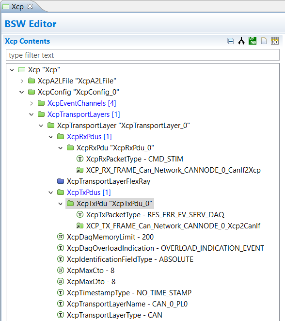
The configuration of Xcp module for BSW generation could be ended here but the third container, XcpA2LFile can also be configured in order to have the RTA-BSW generating an Xcp related A2L file. It can be used along with the complete project in calibration tools such as INCA. In this case only the references to the transport layer have been added to this container.

Step 4. Configure the BswM Action List
The Xcp module needs to be initialized by configuring BswM action list. For more information on the BswM configuration please see the Mode Management workflow on the knowledge base.
Create a new Action Item under the Arbitration Rule “BswM_AR_ReadAllComplete” and Action List “BswM_AL_BswModules_InitListReadAll” and call it “BswM_AI_XcpInit” (if the name cannot be changed in the Abstraction Editor, open up BswMGeneral container to name the action). Select the action kind “BswMUserCallout” and write the function name used in the code.

Now that the BSW modules are configured the BSW code can be generated remembering to edit the configuration and to add the Xcp module generation as shown below:


Step 5. Create a SWC
Adding a SWC is not required for the XCP to work, it is used for the test section.
In our example the RE_Xcp_func_100ms, present in the Xcp_SWC runnable that is added in this step, is used to measure and calibrate two variables written in the XcpSWC.c.
The purpose is to use a calibration variable, Calib_test, that can be modified with INCA and another that is measured, ASW_task_cnt, and that changes only if the value of the calibration one becomes different from zero.
In this example a new SWC will be created with a runnable triggered by a timing event.


Now, a .c file needs to be generated for the runnable entity configured in the component. To do so we can right click on the software component XcpSWC > Generate > Component Code_Frame, a XcpSWC.c file will be generated. This file has to be modified as shown below:

In this file the C code is present for the runnable configured in the XcpSWC. The #include "Xcp.h" is required. The XCP test will measure the variable ASW_task_cnt and calibrate the Calib_test variable. By changing the value of the Calib_test variable and putting it different form zero the measured variable will start to increment.
Now, add the new SWC to the TopLevelComposition by opening the top level composition and add the SWC prototypes as shown below:

Then map it on the existing Ecu Instance "ApplicationECU”, as shown below:


Update the ECU Extract by right clicking on System > System Info > System > Create ECUExtract in the AR Explorer window, now CPT_XcpSWC can be seen in the Top Level composition by clicking on Software> Composition > TopLevelComposition > Open with > Composition overview as shown here:

Step 6. Map runnables to OsTask
Following updates to the BSW Configuration, the RTE Configuration's Runnable to Task Mapping may also need to be updated in the EcucValueCollection. It is recommended that you map all BSW runnables to a dedicated Os task, the runnables, RE_Xcp is mapped on the OsTask_ASW_Period and the XCP SE_MainFunction and all the SE_EventChannels on the OsTask_BSW, as shown below:

After these steps also the RTE can be generated.

Step 7. Update the MCAL
There’s no need to update the Os configuration for this example; the MCAL does need an update since new mailboxes have been added for the Xcp frames. To do so, run the 01_mcal.bat file that contains the mcalgen command with the ..\RTA-SK\ecu_config\bsw\gen\ApplicationECU_Project_Can_EcucValues.arxml file in which the Xcp frames have been added. If we look at the Can_Cfg.h file after the MCAL updates we can see that the two mailboxes used for XCP are added, as shown in the MCAL/src folder:

If this error appears with the mcalgen:

use this specific MCAL version:
RTA-MCAL Generator: Version 1.0.46.28546
Step 8. Build the project
After all these steps, the 02_build.bat file can be run and the .exe file of the project is generated.

If this error appears with the build:

deleting or commenting this lines in all the files present in the directory "VRTA_GCC_Standard/Implementation/RTA-SK/src/bsw/Xcp/integration" will solve the error.
This can be done using the python script "removeIntegrationMacro.py" in the scripts folder.

Step 9. Test with INCA
INCA is used to test the project and try to measure and calibrate.
Step 9.1. Modify the A2L file
The A2L file "Xcp_A2L.a2l" generated in the folder src/bsw/Xcp with the configuration set in "XcpA2LFile" has to be modified in order to perform a test with INCA.
In our example we want to measure the ASW_task_cnt variable written in the XcpSWC.c file, this variable is initially set to zero and increments if the value of the Calib_test variable will be non-zero. The Calib_test variable is the variable that we calibrate with INCA, putting the value of this variable different to zero will change the value of the measured variable which will begin to increase.
Knowing this we need to modify the A2L file by writing the correct addresses of the beginning of the .data section and of the two variables these are found in the file 9.1.0\Targets\VRTA_GCC_Standard\Implementation\Build\build\output.map.
Here is an example of A2L file properly modified: D_RTA-SK.a2l
The first rows of this file have to be copied on the "Xcp_A2L.a2l" as they are without modification until the "/begin MEMORY_SEGMENT" on row 545. This first part contains information regarding the structure of the protocol layer, the Daq, the Daq Event, Pages, PGM, memory segment, CAN parameters and TCP_IP parameters.


The MEMORY_SEGMENT AppCode is the region that has to be modified in function of the output.map file:
- Write on row 550 the address related to the begin of .data section that is written in the output.map file;
- Write on row 560, 579, 580, 593 the address related to the Calib_test variable that is written in the output.map file;


Also the last part of the code written in "D_RTA-SK.a2l" as to be modified in function of the address of the Calib_Test and ASW_task_cnt variables:
- Write on row 765 the address related to the Calib_test variable that is written in the output.map file;
- Write on row 781 the address related to the ASW_task_cnt variable that is written in the output.map file.

Step 9.2. Create a virtual OCD file
INCA is unable to recognize our virtual target as it performs optimizations for ETAS that do not allow it to be recognized. To bypass this problem, a VirtualOCD.xml file is created which describes a Kvaser target through which INCA is able to recognize the virtual target.
Here is the Virtual OCD.xml file: VirtualOcd.xml
And save it in this location: C:\Program Files (x86)\ETAS\BOA_V2\Bin\Win32\Dll\ServerOCDs
Step 9.3. Experiment
Now, open INCA and create a top folder by right click on the window 1 Database Objects and then click on Add > Add Top Folder as shown in the below image:

Call it XCP_test and add a Workspace by right clicking on the top folder created and clicking Add > Workspace

Now add the A2L file by clicking on the plus green sign in the window 4 Project/device:

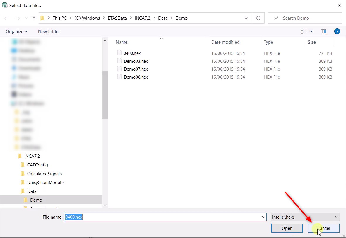
A new window will open, click on Add and select the A2L file and click on Open.

Now INCA asks for an .hex file but it is not required to test the XCP so click on Cancel and finally click OK.
A new window will open asking for a device, select the Kvaser USBCAN Professional > CAN > XCP and click OK

If the Kvaser device will not appear inside the "add new device for the project" window, a "AddOn_3rdPartyHardware" plugin need to be installed.
After these steps we can open the Hardware window by clicking on the blue icon in section 5 Hardware

A new window will open and now the initialization of the hardware is possible but before doing that run the Loopback server (Debug\runLoopback.bat) and the executable (Build\output\RTA-SK_VRTA.exe) of the project.
Click on the button Initialize hardware as shown here:

The window connect devices will open, click OK

After this step the ECU is connected and allows the calibration

Now click on the button Manage memory pages and in the Memory pages window select 2 Enhanced, action: Upload and then click on Do it, as shown below:


Now the experiment can be run, click on the Experiment button

The experiment window will open, now add the variables by clicking on Variables > Variables Selection and select both of them, they will be open in two overlapping window, move a window to see them both


Finally the experiment can start by clicking on the play button and changing the value of Calib_Test. The value of ASW_task_cnt should now increment when Calib_test is non-zero.

