1. Contents
2. Scope
This use case describes the creation of a multicore RTA-CAR project.
The steps required to create and initially configure an RTA-CAR project are covered in the RTA-CAR Sample Workflows section of the RTA-CAR 9.2.0 User Guide, so in this use case we use an existing single core project as our starting point, which is based on the VRTA_Standard Starter Kit (SK) for RTA-CAR, and we extend that sample project to be multicore.
If you wish to follow along with this use case, you will need to import the aforementioned SK into your ISOLAR-AB workspace.
Although this use case describes the "conversion" of a single core project to multicore, we would not generally recommend this as an appropriate method for creating a multicore project. The initial use of a single core project as the starting point has been done only to simplify the example workflow.
Multicore projects usually require deep analysis and pre-planning, and the more likely scenario is that a brand new project would be created and immediately configured as multicore. We strongly recommend that you do not try to "convert" a single core project to multicore.
3. Definitions and Abbreviations
BSW: AUTOSAR Basic Software, Hardware independent service layer.
RTE: AUTOSAR Real Time Environment.
OS: AUTOSAR Operating System.
SWC: Software Component.
AR: AUTOSAR
AN: Application Note
ECU: Electronic Control Unit
ASW: Application SoftWare
PIM: Per Instance Memory
RE: Runnable Entity
ConfGen: Configuration Generation (BSW config tool)
4. Toolchain and Prerequisites
It is assumed you are using the RTA-CAR 9.2.0 toolchain:
RTA-CAR 9.2.0 toolchain | |
|---|---|
| ISOLAR-AB | v 9.2.0 |
| RTA-RTE | v 7.5.0 |
| RTA-BSW | v 6.1.2 |
| RTA-OS | v 6.2.0 |
The workflow below is designed to be stand-alone and it does not have any prerequisites beyond the import of the SK. It is assumed that you are already familiar with how to create and configure an AUTOSAR project with ISOLAR-AB.
If you’ve not done so already, we recommend that you review (and optionally work through) Workflows 01, 02 and 03 to gain a better understanding of ISOLAR-AB and the tools available to create and configure an AUTOSAR project.
5. Workflow Summary
As illustrated in the diagram below, in this sample workflow we are going to create a basic multicore environment, which is comprised of two cores (Core0 and Core1) and two SWCs (MasterSWC running on Core0 and Core1SWC running on Core1).
The multicore functionality will be demonstrated with a simple communication between the two SWCs, with MasterSWC sending a Test Code to Core1SWC, and Core1SWC responding to MasterSWC with a Test Result.
Using the imported SK as our starting point, the workflow will take you through the process of creating and configuring the new Core1SWC, and also adding additional configuration to the MasterSWC (which is already included in the SK).
The step-by-step guide will also show you how to create and configure all the requisite elements for a multicore environment, including the aforementioned Partitions and OsApplications. We’ll also see how to create the Runnables for the SWCs, how to map them to the required OsApplication, thus determining the Core on which they will run.
The multicore functionality will also include the use by Core1SWC (running on Core1) of a BSW service (NvM), running on Core0.

Here is a summary of the steps that you will be working through in this example.
- Step 1. Update the SK ASW
- Step 1.1 Create Core1SWC
- Step 1.2 Configure SWCs with the required Interfaces
- Step 1.2.1 Create the S/R Ports for Core1SWC
- Step 1.2.2 Create the S/R Interface Ports for MasterSWC
- Step 1.2.3 Additional Configuration
- Step 1.2.4 Add a Service Port to NvM
- Step 1.3 Create and configure Internal Behaviour for Core1SWC
- Step 1.3.1 - Create Internal Behaviour for Core1SWC
- Step 1.3.2. Add a Memory PIM (PerInstanceMemory) to Core1SWC
- Step 1.3.3. Add a Service Needs for NvM to Core1SWC
- Step 1.4 Create a new Runnable for Core1SWC
- Step 1.5 Add Data Access Points to Runnables
- Step 1.5.1 Adding Data Access Points to RE_Main_Core1
- Step 1.5.2 Adding Data Access Points to RE_RunTest
- Step 1.6 Add NvM Server Call Point to Core1SWC
- Step 1.7 Create new Data Receive Events
- Step 1.7.1 Add a DataRecievedEvent for MasterSWC
- Step 1.7.2 Add a DataRecievedEvent for Core1SWC
- Step 1.8 Manually connect the Interfaces and Ports
- Step 1.8.1 - Add Core1SWC to the TopLevelComposition
- Step 1.8.2 Connect MasterSWC PPort to Core1SWC RPort
- Step 1.8.3 Connect Core1SWC PPort to MasterSWC RPort
- Step 1.8.4 Connect NvM PPort to Core1SWCsterSWC RPort
- Step 1.8.5 Create and configure NvM block descriptor
- Step 2. Update OsNumberOfCores
- Step 3. Create required Elements
- Step 3.1 Creating new Partitions
- Step 3.2 Creation and Assignment of OsApplications
- Step 3.2.1 Creating the OsApplications
- Step 3.2.2 Assigning the OsApplications
- Step 3.3 Creation of Core Definitions
- Step 3.4 Additional OsApplication Configuration
- Step 3.4.1 Assign newly created definitions
- Step 3.4.2 BSW Configuration
- Step 4. Create additional OsTasks
- Step 4.1 Create the OsTasks
- Step 4.2 Set the Os Application for each Task
- Step 5. Map SWCs to OsTasks
- Step 5.1 Mapping Runnables to Tasks
- Step 5.2 Map the EcuM_MainFunction to both Cores
- Step 5.3 Map NvM Service Events
- Step 6. RTE Generation
- Step 7. Additional OS Configuration
- Step 7.1 Update OS Command
- Step 7.2 Update Target Specific Configuration
- Step 7.3 Create Os Resources
- Step 7.4 Referencing RTE Created Os Objects
6. Workflow
Understanding Multicore
The primary benefit of a multicore system is the potential to improve performance when compared to a single core equivalent, but this performance gain may not always be realized. In some circumstances, system performance can even be adversely affected by a switch from single core to multicore.
In general, however, performance can be improved in a multicore system because the ASW is split across two or more cores, allowing the CPU load to be distributed across those cores.
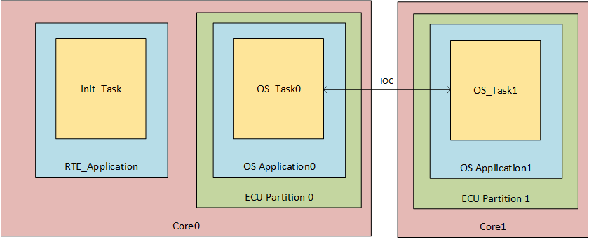
As shown in the diagram below, the two main elements required in a multicore configuration are as follows:
ECU Partitions. In a multicore system, at least one ECU Partition must be assigned to each core. In the most basic example (like the one below), there might be two cores in the system, and each one has just a single ECU Partition assigned to it.
OsApplications. These are used to define the privilege level and the protection boundary of the tasks and ISRs that they own. In a multicore context, there is at least one OsApplication for each ECU Partition. This allows us to maintain separation between the Os Tasks and Elements assigned to each core.
This simple diagram illustrates the relationship between ECU Partitions, OsApplications and Os Tasks on a core, and between the cores in a multicore system.
Step 1. Update the SK ASW
In this first step, we are going to update the imported SK as follows:
We're going to create a new SWC called Core1SWC (which we will later map to Core1) and configure it with the S/R Ports required for it to communicate with MasterSWC.
We're going to configure MasterSWC (which is already part of the SK, and which we will later map to Core1) with the S/R Ports required for it to communicate with Core1SWC.
As our sample multicore functionality includes the utilisation by Core1SWC of a BSW service (NvM) we'll be configuring Service Ports for this on Core1SWC itself, and also on the existing NvM, which is already part of the SK.
We also need to do some additional configuration of Core1SWC, including adding a Memory PIM and Service Needs for NvM, and creating a Runnable for it.
The SK already includes the Runnable that will be used by MasterSWC, so there's no need to create a new one, however both Core1SWC and MasterSWC's Runnables require further configuring with Data Access Points for Transmission and Reception and Data Receive Events.
Once all the above configuration is done, we will then manually connect all the newly-created ports.
After the above configuration, our project will look like this (although at this point the actual Cores have not yet been created).

Step 1.1 Create Core1SWC
We'll begin by creating Core1SWC.
Right click on "Software" and select Create Component --> Elements | Application Sw Component Type

Call the new SWC "Core1SWC" and place it in a new ARPackage called "Core1SWC.arxml" inside the folder asw_config.

When creating your own projects, we recommend that you create a separate arxml file for each SWC, which will make it easier to reuse those SWCs in other projects. This can be done by using a different file name for each Application Sw Component Type that you define.
Step 1.2 Configure SWCs with the required Interfaces
Our new Core1SWC will communicate with MasterSWC via Sender/Receiver ports, so both SWCs will need a new PPort and RPort for this communication.
The interfaces required to define the data types for this communication already exist in the SK, so we do not need to create them as part of this workflow.
Step 1.2.1 Create the S/R Ports for Core1SWC
Open Core1SWC with the component editor.
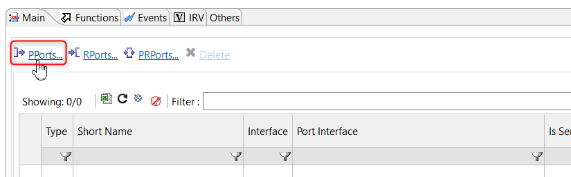
In the "Main" tab, click PPorts...
In the "Port Creation Dialog", select the interface type as 'Sender Receiver' and then select the SR_IF_TestResult Port Interface (which already exists in the SK), and click Finish.

After creating the Port, and when you return to the Main tab, you can then modify its name by double-clicking inside the "Short Name" column. Set its name to 'PPort_TestResultCore1'.

Now click on the RPorts link and repeat the above steps, this time choosing the SR_IF_TestCode Interface, and setting its name to RPort_TestCode1Core1.

And finally, repeat the process once again, clicking again on RPorts. This time set the interface type as 'Client Server' and select the NvM_Service Interface. Re-name it to RPort_NvMCore1.

Step 1.2.2 Create the S/R Interface Ports for MasterSWC
You then need to repeat the above steps to add the corresponding PPort and RPort to the existing SK MasterSWC.
In this case, the outgoing Test Code will be mapped to a PPort (called PPort_TestCode1Core1), and the incoming Test Result will be mapped to an RPort (RPort_TestResultCore1).
Once the above configuration is completed, MasterSWC will have the Ports required to allow it to send a Test Code to Core1SWC (and receive a response), and Core1SWC will have the Ports required to receive the Test Code from MasterSWC (and send back the response).
Here is a screenshot of the MasterSWCs ports, after creating the 2 additional ports required to communicate with Core1SWC.

Step 1.2.3 Additional Configuration
Our multicore functionality will also include the utilization by Core1SWC, of a BSW service (i.e. NvM), so we need to do the following:
- Add a Service Port to the existing SK NvM
- Add a Memory PIM (PerInstanceMemory) to Core1SWC
- Add a Service Needs for NvM to Core1SWC
Step 1.2.4 Add a Service Port to NvM
The SK already includes a pre-configured NvM, but we need to add a PPort to allow the communication with Core1SWC (we’ll be adding the corresponding RPort to Core1SWC later in step 1.6).
Double-click on the NvM Service SWC to open it in the "Component Editor".

Click the PPorts... link, then in the "Port Creation Dialog" set the interface type as 'Client Server' and select the NvM_Service Interface. Now select Finish.
Rename the new PPort to NVM_NativeBlock_3 so that it is consistent with the existing NvM Service ports in the SK.

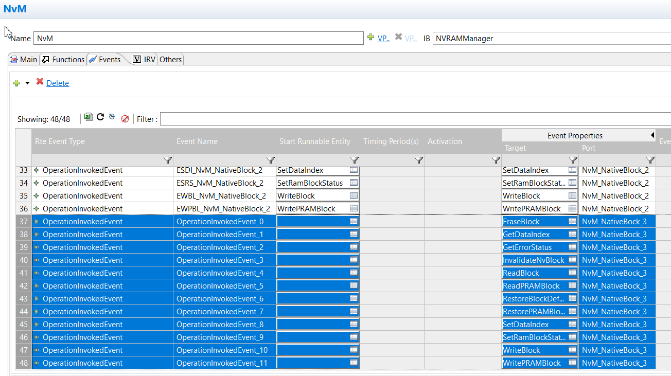
We now need to add Events for our newly created NvM Service Port.
Switch from the "Functions" tab to the "Events" tab, open the drop down menu next to the green "add" button, and select OperationInvokedEvent.
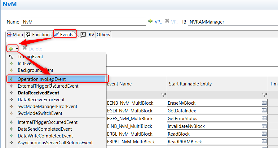
In the "OperationInvokedEvent Creation Dialog" select the NvM Services you wish to access in Core1SWC (we've selected all of them) and set the Port as NvM_NativeBlock3, then click OK.

When you return to the "Events" tab you’ll see all the events you've just created.
Step 1.3 Create and configure Internal Behaviour for Core1SWC
Step 1.3.1 - Create Internal Behaviour for Core1SWC
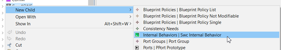
We now need to create a new Internal Behaviour container for Core1SWC within which we will then create a new Runnable.
Right click on Core1SWC and select New Child → Internal Behaviours | Swc Internal Behaviour.
The new container will be added to the AR explorer as a new child. You'll be prompted to enter its name, but there is no need to do that at this stage. Just double click on the new container to open it.

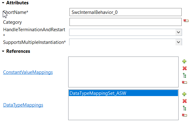
Set the new container's properties as follows:
- Shortname: Leave as SwcInternalBehavior_0.
- DataTypeMappings: Click the "+" and add a reference to DataTypeMappingSet_ASW (this already exists in the SK).
Step 1.3.2. Add a Memory PIM (PerInstanceMemory) to Core1SWC
We need to add a Memory PIM (PerInstanceMemory) to Core1SWC so that during testing we'll be able to change a value in memory and then make a call to set the RAM Block to "changed". This will allow us to test the NvM functionality in a separate Core.
Open the Core1SWC in the "Component Editor", switch to the Others tab. You will see the message 'Please select Internal Behavior to view the additional properties'.

Select the small green plus sign next to the drop down box labelled 'IB'. This will create an internal behavior for SWC. Leave the name as the default value.

You should now be presented with a new view. Select the 'PerInstanceMemory' option from the 'IB Elements' box on the left.

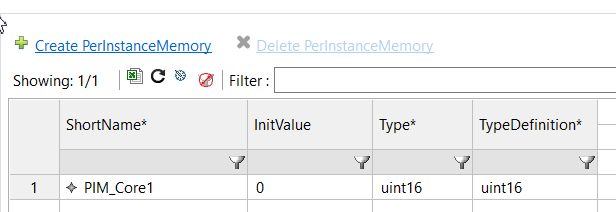
Click the Create PerInstanceMemory link to create a new instance in the table.
- Change the instance's ShortName to "PIM_Core1".
- The Type and TypeDefinition will be blank by default, so you'll need to set these both to uint16.
Step 1.3.3. Add a Service Needs for NvM to Core1SWC
And finally we need to add a Service Needs for NvM to Core1SWC. This is required to define exactly what the Core1SWC requires from the BSW service.
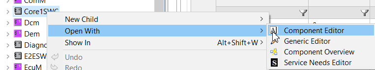
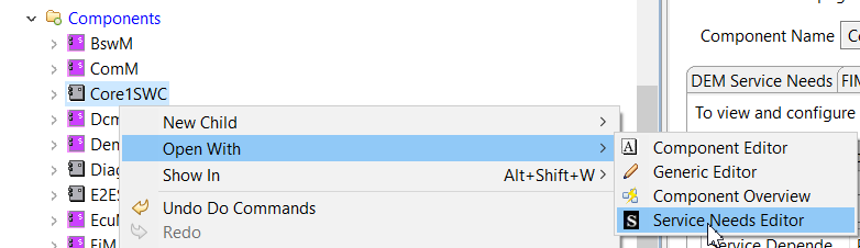
Right click on Core1SWC in the AR Explorer and select Open With → Service Needs Editor.
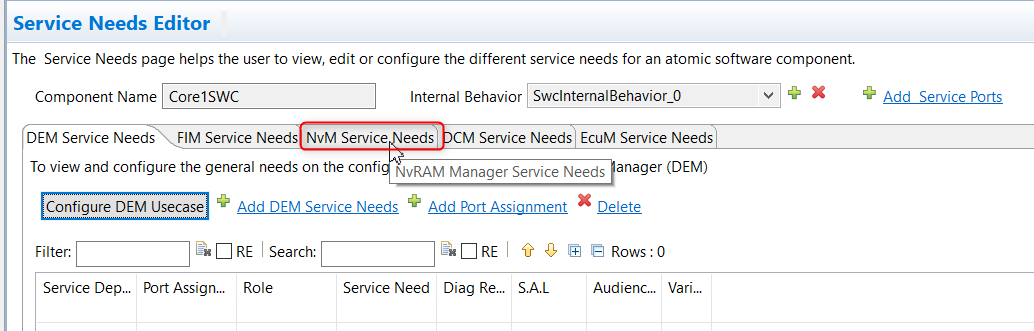
Select the "NvM Service Needs" tab.
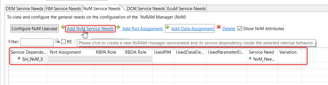
Click Add Nvm Service Needs to create a Service Needs instance and name it as Srv_NvM_0.
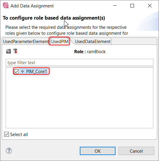
Select the new instance, click Add Data Assignment, and when you're in the "Add Data Assignment" dialog, select the UsedPIM tab. Select the PIM we created earlier (PIM_Core1) then click OK.
Back in the "NvM Service Needs" editor, on the right-hand side, change the settings for this Service Needs as shown here.

Step 1.4 Create a new Runnable for Core1SWC
With the Internal Behaviour container now created for Core1SWC, we can create a Runnable entry within it.
Open Core1SWC with the "Component Editor" and switch to the Functions tab.

Once in the Functions tab, click Runnables to create a new Runnable, and then change its name to RE_Main_Core1.

Step 1.5 Add Data Access Points to Runnables
Runnable Entities require Data Access to have access to SWC ports, so we need to create Data Access Points for the RE_Main_Core1 runnable that we created above, and also for the RE_RunTest runnable (in MasterSWC), which is already part of the SK.
Step 1.5.1 Adding Data Access Points to RE_Main_Core1
First we will create the Transmit and Receive Data Access Points required by the RE_Main_Core1 runnable.
Data Access Point for Transmission
The RE_Main_Core1 runnable will transmit Test Result data (to the RE_RunTest runnable in MasterSWC) on the PPort that we created in step 1.2.1, which means the Data Access will need to be a Data Send Point.
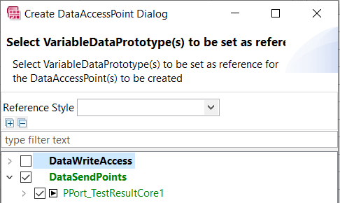
Switch to the "Data Access Points" subtab and then click Access Points to add a new Access Point.
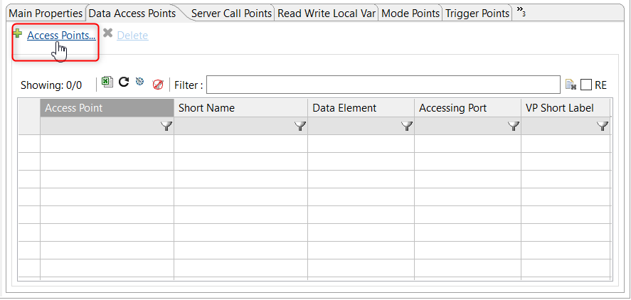
In the "Create DataAccessPoint Dialog" dialog, select DataSendPoints, which will automatically select PPort_TestResultCore1.
Data Access Point for Reception
The RE_Main_Core1 runnable will receive the Test Code (from the RE_RunTest runnable in MasterSWC) on the RPort that we created in step 1.2.1, which means the Data Access will be a Data Receive, so repeat the above steps to add a new Access Point, select DataRecievePointByArguments in the Create DataAccessPoint dialog, then click OK.
Step 1.5.2 Adding Data Access Points to RE_RunTest
We now need to repeat the above steps for the RE_RunTest runnable in MasterSWC which, as previously noted, already exists in the SK.
Open MasterSWC in the "Component Editor" and select the Functions tab.

The RE_RunTest runnable will already be listed, so select it, then select the "Data Access Points" tab as previously described, then click Access Point to create the new Data Access Point.
Data Access Point for Transmission
The RE_RunTest runnable will transmit the Test Code to the RE_Main_Core1 runnable via the PPort that we created in step 1.2.2, and this means that we need a Data Send Point. So, in the "Create DataAccessPoint Dialog", make sure that DataSendPoints is ticked and that PPort_TestCodeCore1 is selected.

Data Access Point for Reception
The RE_RunTest Runnable receives the Test Result from the RE_Main_Core1 Runnable via the RPort that we created in step 1.2.2, so we need to select DataReceivePointByArguments and make sure that RPort_TestResultCore1 is selected.

Step 1.6 Add NvM Server Call Point to Core1SWC
In step 1.2.3 we added a Service Port to NvM to receive communications from Core1SWC. We now need to add into Core1SWC the corresponding Server Call Point to NvM.
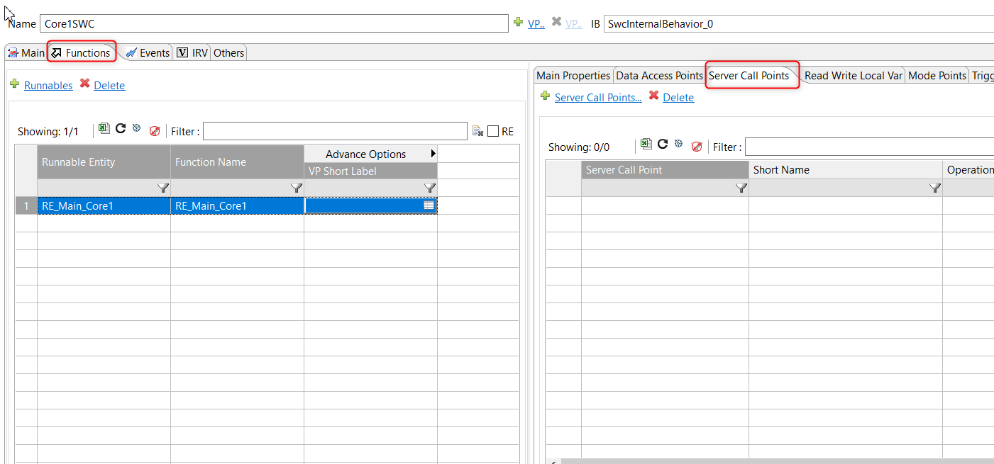
Open Core1SWC in the "Component Editor", switch to the Functions tab, go to the Server Call Points sub-tab on the right and click on the Sever Call Points... link.
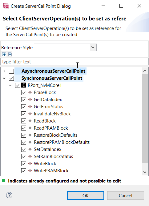
In the "Create ServerCallPoint Dialog" select "SynchronousServerCallPoint" and select the RPort_NvMCore1 port for receiving NvM Services, then select OK.
Step 1.7 Create new Data Receive Events
Runnables can only be executed if they are connected to an Event, so we now need to create new Data Receive Events for our two Runnables.
Step 1.7.1 Add a DataRecievedEvent for MasterSWC
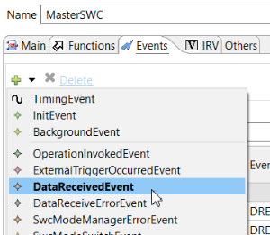
To create a DataRecievedEvent for MasterSWC, switch from the "Functions" tab to the "Events" tab, open the drop down menu next to the green "Add" button, and then select DataRecievedEvent.
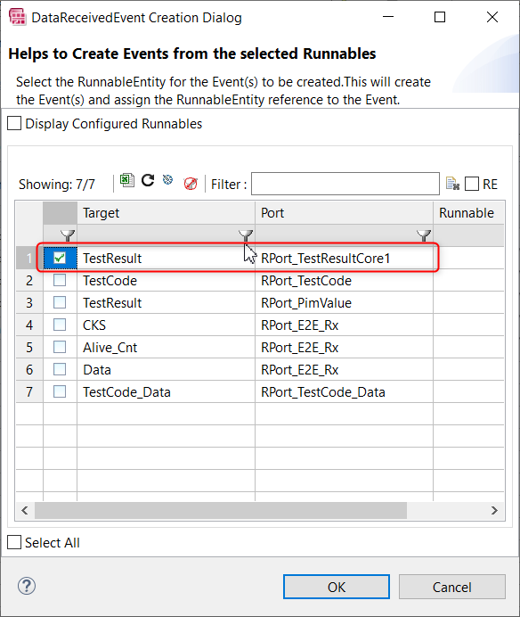
In the "DataRecievedErrorEvent Creation" dialog, select the MasterSWC RPort that is related to the incoming test result from Core1SWC (RPort_TestResultCore1), then click OK.
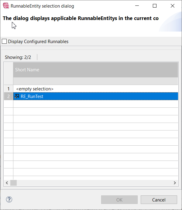
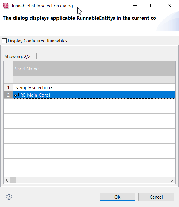
In the "RunnableEntity selection dialog", select the RE_RunTest runnable.
Step 1.7.2 Add a DataRecievedEvent for Core1SWC
We now need to repeat the above steps to create an event in Core1SWC, and this time it will be the Test Code being received from MasterSWC that will trigger the runnable.
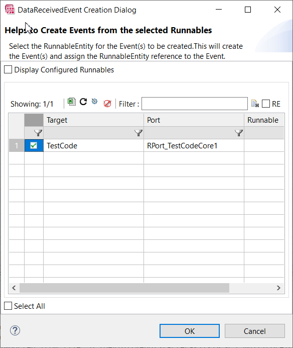
And the runnable we select is RE_Main_Core1.
With all the above configuration steps completed, our new Core1SWC has the required Interfaces to communicate with MasterSWC and with the NvM Service Component, as well as a PIM configuration and NvM Service Needs to the SWC so that we can include in our example project the IOC (see step 6) and the utilization of BSW services from a second core.
Step 1.8 Manually connect the Interfaces and Ports
Step 1.8.1 - Add Core1SWC to the TopLevelComposition
Open the Top Level Composition in the Composition Editor and click the down arrow next to the small green plus sign. Select Component Prototype in the drop down menu that appears.

In the dialog that opens up, select Core1SWC from the table and select OK.

Now navigate to the "Manual Connection Editor" tab at the bottom.
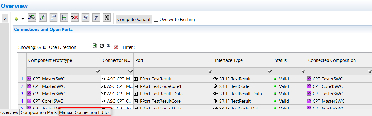
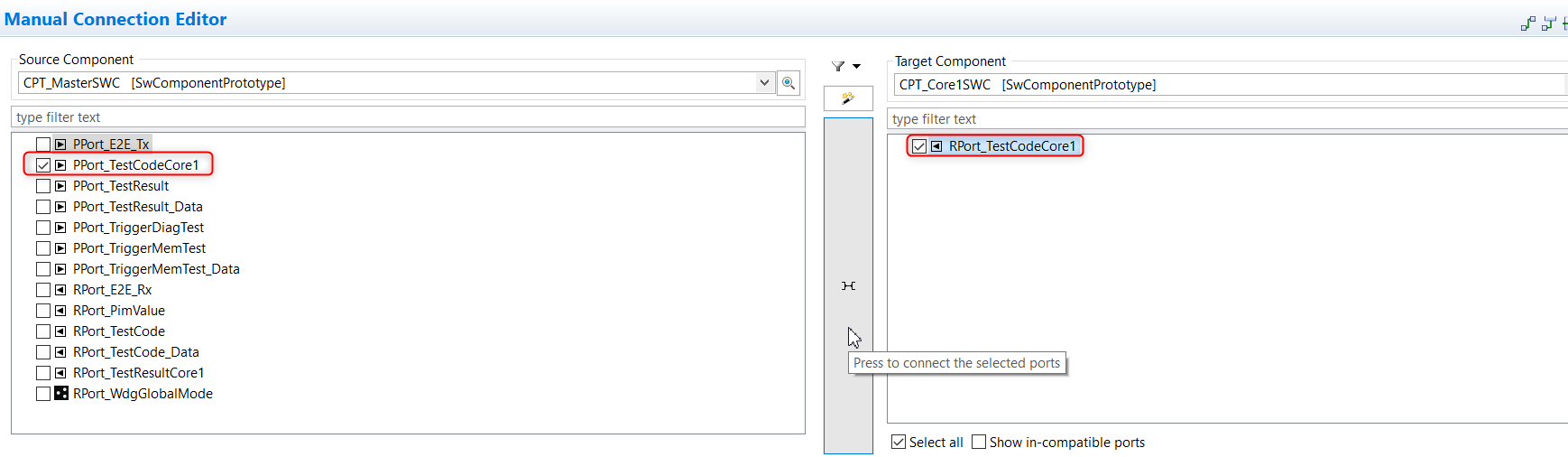
Step 1.8.2 Connect MasterSWC PPort to Core1SWC RPort
In the Source Component dropdown on the left, select MasterSWC, and then tick the PPort_TestCodeCore1 Port that we created in step 1.2.2.
Then, in the Target Component dropdown on the right, select Core1SWC and tick the RPort_TestCodeCore1 Port that we created in step 1.2.1.
Then manually create the connection between the two ports by clicking the connector icon.
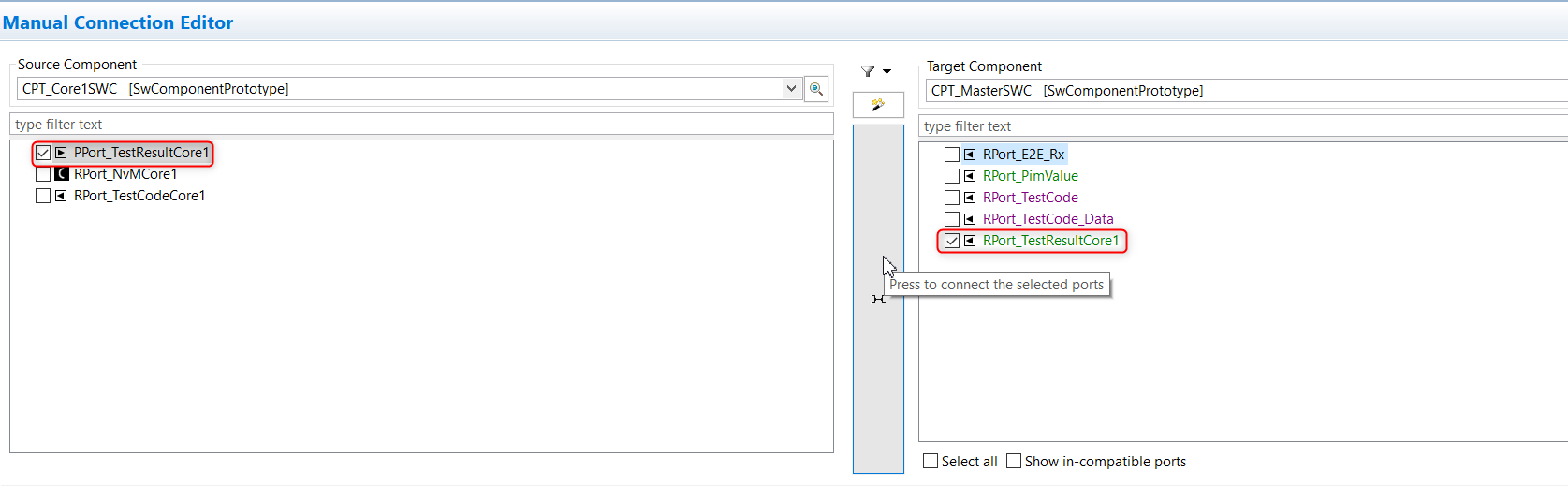
Step 1.8.3 Connect Core1SWC PPort to MasterSWC RPort
Repeat the above steps for the passing of the Test Result from Core1SWC's PPort to MasterSWC's RPort, as shown here.
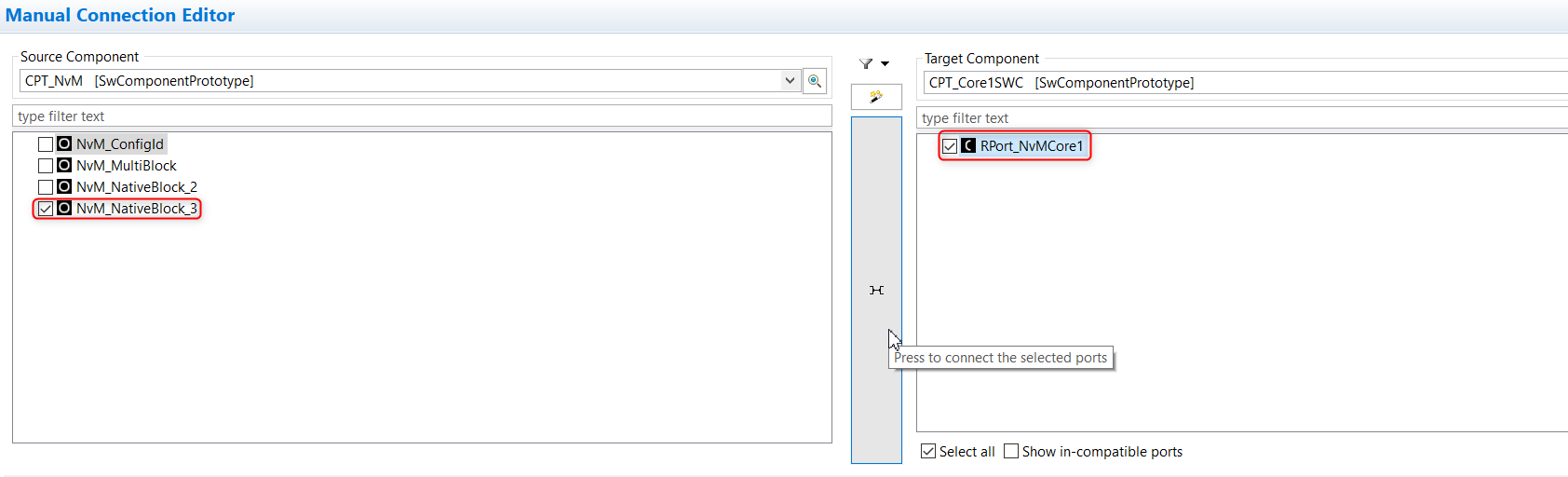
Step 1.8.4 Connect NvM PPort to Core1SWCsterSWC RPort
And repeat the steps again for the Nvm Services from NvM's PPort to Core1SWC's RPort.
Step 1.8.5 Create and configure NvM block descriptor
We now need to create the NvMBlockDescriptor. This will describe how the new NvM block will behave.
First open the NvM module in the BSW editor by double clicking on the NvM module within the BSW modules section.

Then expand 'NvM "NvM"' and right click on the section called NvMBlockDescriptors and select Create NvMBlockDescriptor.

In the newly created NvMBlockDescriptor, configure the values so they match the screenshot below.

Step 2. Update OsNumberOfCores
We're almost ready now to begin the multicore specific configuration of our example project.
However, as a prerequisite to creating a multicore system, we first need to update our BSW configuration so that it is aware that it is working in a multicore system (EcuM has to be mapped to both cores to handle startup, shutdown, init phases etc).
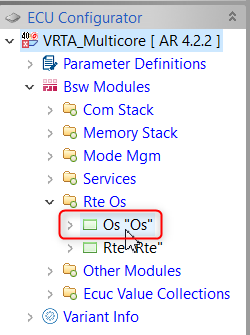
Double-click the Os module in the ECU Navigator.
Under the OsOS container, change the OsNumberOfCores parameter to 2:

The OsNumberOfCores parameter will be checked by the BSW code generator, and having it set to 2 will result in the generation of a second instance of the EcuM Mainfunction (which, as you can see here, will be mapped in the second Core).

We'll deal with the actual mapping of the EcuM Mainfunctions later, in Step 5.
For now, having made the change to OsNumberOfCores, you need to run the Configuration Generation (Confgen) and the Code Generator for RTA-BSW.

In earlier versions of ISOLAR-AB it would have been necessary at this point once again to update the ECU Extract, but this is now done automatically within the Configuration Generation (ConfGen) process.
Step 3. Create required Elements
The next step is to update the System Configuration with Partitions and OsApplications (as described in the Introduction) and also Core Definitions, which are reference points to represent each physical core on the target (used in the OS generator).
Step 3.1 Creating new Partitions
Open your ECU Extract with the "ECU Partition Editor".

You'll be prompted to select the ECU Extract for the ECU when opening this editor for the first time.
At the top of the editor, switch to the "Multicore" Workflow Filter.
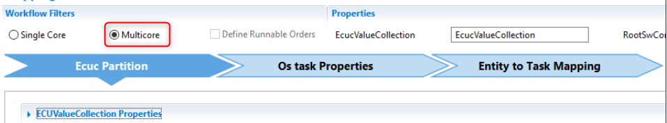
Create the first new Partition by clicking on the "+" icon at the top right of the editor and then select CreateEcucPartition.


As shown below, we now have two blank entries in the partitions table with the default names of EcucPartition_0 and EcucPartition_1.
Step 3.2 Creation and Assignment of OsApplications
In this next step we're going to create the required OsApplications and then assign them to an EcuC Partition.
Step 3.2.1 Creating the OsApplications
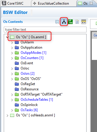
From the ECU Navigator, double-click on the Os module.

Instead of modifying the OsNeeds.arxml file (which is automatically generated) we'll be using the same Os.arxml file that we used earlier for the OS configuration.
Click the split configuration icon and check to ensure you're working in the expected file.
Right click the uppermost Os container, then select New Child → OsApplication
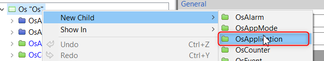
This will create an empty OsApplication Container with a default name of OsApplications.
We need to create 3 separate OsApplications, one for each of our two Cores from where we will map our OsTasks (OsApplication_0 and OsApplication_1), and a third (RTE_Application), which will contain InitTask, which is part of the SK, and which is used to start EcuM, SchM and BswM.
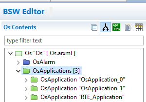
Once we have the three OsApplications, as shown in the images below, we can complete the configuration by setting the references to the appropriate EcuC Partition.
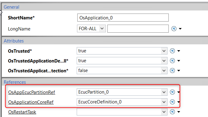
- OsApplication_0 will be referenced to EcucPartition_0 (for Core0)
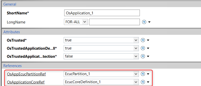
- OsApplication_1 will be referenced to EcucPartition_1 (for Core1)
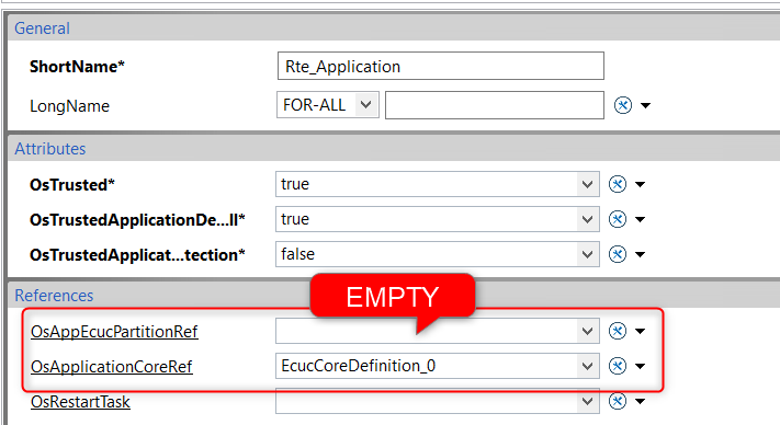
- Rte_Application does not require a reference to an EcuC Partition
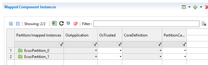
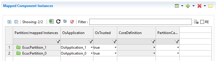
Step 3.2.2 Assigning the OsApplications
We now need to assign OsApplication_0 to EcucPartition_0 and OsApplication_1 to EcucPartition_1. First, re-open the ECU extract in the Ecuc Partition editor, then configure the two partitions like in the below screenshot.

In the dialog box that pops up, place the new Core Definition in the same file 'Partitions.arxml' that we created for the partitions.

Repeat this for EcucPartition_1. The end result should look like the below screenshot.

We first need to set the following mandatory parameters within the OsApplication container to the values indicated:
- OsTrusted: TRUE
- OsTrustedApplicationDelayTimingViolation: TRUE
- OsTrustedWithMemoryProtection: FALSE
OsTrustedWithMemoryProtection specifies whether an OsApplication is given memory protection in scalability classes 3 or 4. Configuring it to TRUE would involve providing functionality (via Os call outs) to decide whether calls to read/write to specific memory sections are allowed, so for this reason we're configuring it here as FALSE to simplify the sample workflow.
Configure OsApplication_0 like this:
OsApplication_1 like this:
And Rte_Application like this:
Step 3.4.2 BSW Configuration
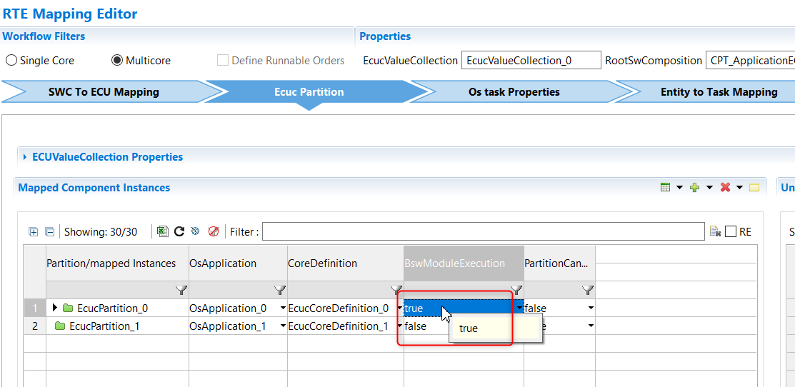
Set EcucPartition_0 as the host for BSW modules
We first need to set EcuCPartition_0 as the Partition that will contain all of the BSW modules, and we do this by setting BswModuleExecution to TRUE.
Map SWCs and BSW Modules to Ecuc Partitions
And then we can begin dragging and dropping SWC instances between the two partitions. As you can see in the example below we are mapping only Core1SWC to EcucPartition_1, and everything else (including MasterSWC and all the yellow folders for BSW modules) to EcucPartition_0.
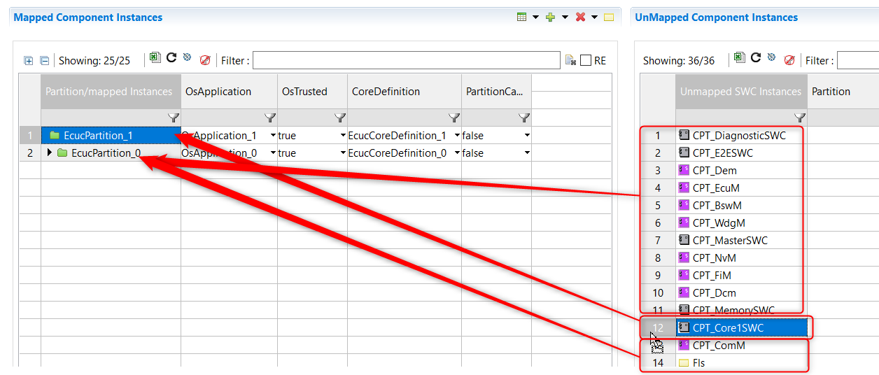
The end result will look like this.

Step 4. Create additional OsTasks
The new Runnables we created inside Core1SWC (in Step 1.4) do not yet have a corresponding OsTask contained within an OsApplication, which is required in order for them to be scheduled to run, and to specify on which core they will run.
So, we need to create the following two new OsTasks:
- OsTask_ASW_Core1 will be for the additional ASW code within our new Core1SWC (and will be run on Core1).
- OsTask_Events will be for the NvM Service Runnables which we will call from Core1SWC and which will run on Core+0.
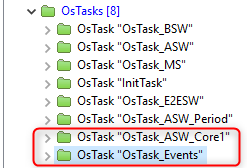
The OsTask for the MasterSWC Runnable (OsTask_ASW) is already included in the SK.
Step 4.1 Create the OsTasks
In the BSW Editor, double-click on Os in the ECU Navigator, then right click on the Os container and select OsTask.

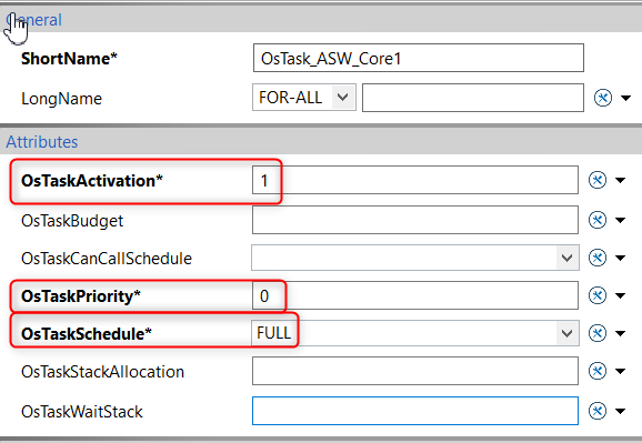
As noted above, the first new task (OsTask_ASW_Core1) will be for the additional ASW code within our new Core1SWC, and the second (OsTask_Events) will be for the NvM Service Runnables.
Configure the mandatory parameters for both tasks as shown here.
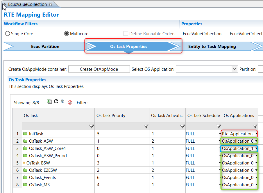
Step 4.2 Set the Os Application for each Task
We then need to map each of our new OsTasks to the appropriate OsApplication. We'll be assigning one of the tasks to OsApplication_0 and one to OsApplication_1, essentially assigning them to run on Core0 and Core1 respectively.
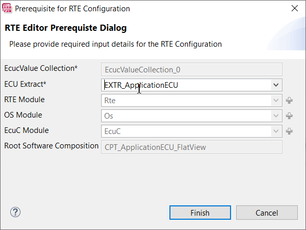
Right click on the Extract and select Open With → RTE Editor

Go to the "Os Task Properties" tab and assign the appropriate Os Application to each OS Task, as follows:
- OsTask_ASW_Core1 is mapped to OsApplication_1
- OsTask_Events is mapped to OsApplication_0
- InitTask is mapped to Rte_Application
Step 5. Map SWCs to OsTasks
Now that we have each OsTask assigned to the appropriate OsApplication, we can assign the SWC's Runnables to the Tasks.
Assuming you've followed all the previous steps, you should have two EcuM Mainfunctions (one for each Core) and the runnable RE_Main_Core1 in Core1SWC on Core1.
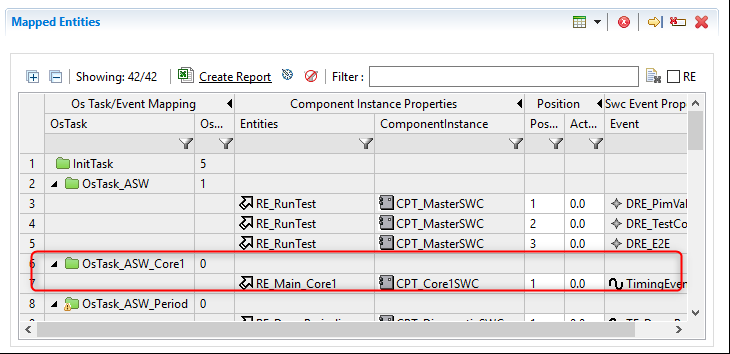
Step 5.1 Mapping Runnables to Tasks
First we need to map the RE_MainCore1 Runnable to OsTask_ASW_Core1 so that the ASW for Core1SWC will be scheduled in Core1.
Step 5.2 Map the EcuM_MainFunction to both Cores
Then, as mentioned in Step 2, the EcuM will be mapped to both cores, so we will now also map the EcuM Mainfunction to both OsTask_AWS_Core1 and also OsTask_BSW.
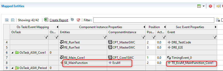

As you can see from the above images, you can distinguish between the two EcuM_Mainfunctions by looking at the name in the "Swc Event Properties" column (the name includes the name of the Core).
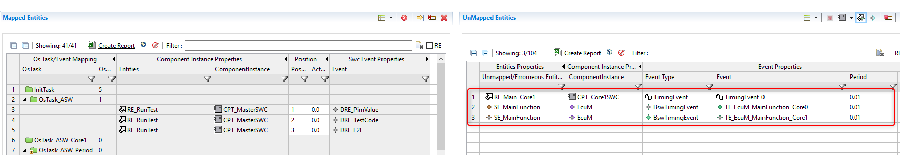
Step 5.3 Map NvM Service Events
We added Service Needs for NvM to Core1SWC in step 1.2.3, so we also now need to map the NvM Service Events to the other tasks for OsTask_BSW on Core 0.
By default, NvM Service Events are hidden in the "Unmapped Entity" table, so click the icon shown below to reveal them. You can filter by the event name to see the set of events relevant to NativeBlock_3, which is the one used by NvM in our example (Step 1.2).
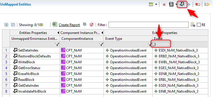
Select all the above events and map them to the OsTask_Events task on Core0.

Step 6. RTE Generation
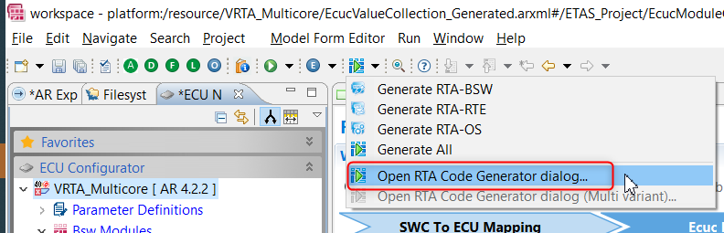
We've completed the multicore configuration, and we're now ready for the RTE Generation.
Open the RTA Code Generator options via the icon on the toolbar.
Replace the Rte Command line with the following string:
|

Switch to the "Included AR Files" tab and ensure that the newly added Partitions.arxml and Core1SWC.arxml files have been selected.
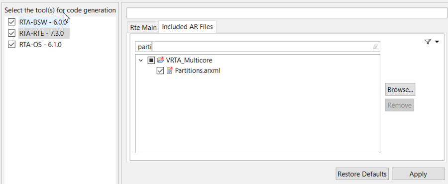
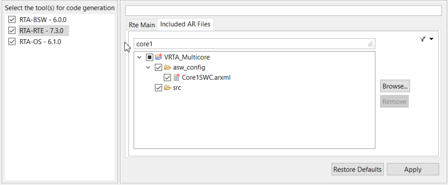
Now generate the RTE.

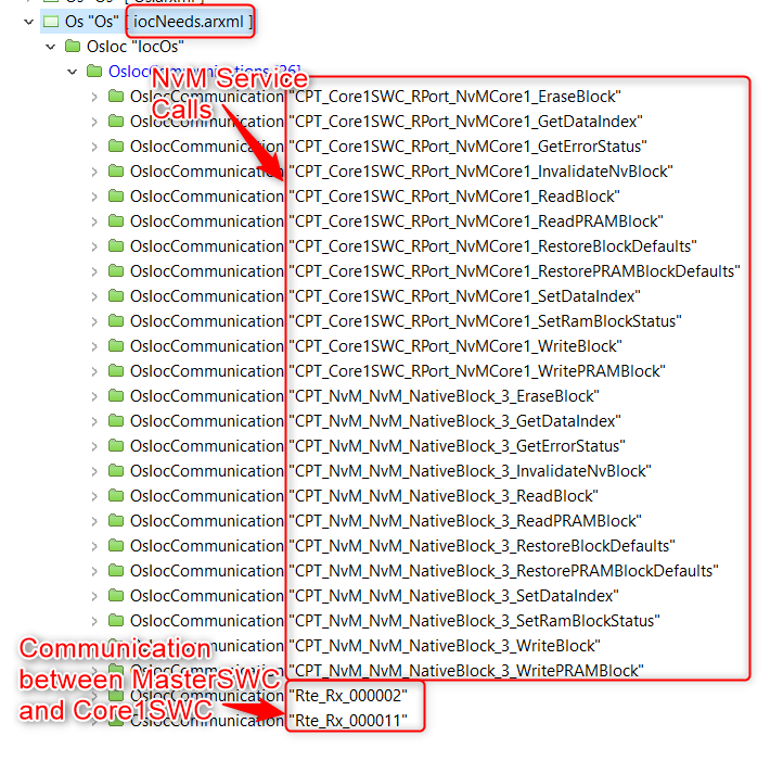
Following a successful completion, you'll notice that a new iocNeeds.arxml file has been generated under the Os Container.
If you open the file, you'll see new elements describing the Inter Os Application Communication (IOC) interfaces required for our multicore system. We’ll be using this file in Step 7.
Step 7. Additional OS Configuration
We now need to update the Os configuration with additional information for our multicore project, including the number of cores and stack allowances for OsApplications/tasks etc.
Step 7.1 Update OS Command
In our example project we're using the VRTA Target, which requires an additional command line option to create virtual cores.
Open the RTA Code Generator Dialog:

Replace the command line options for the Os with the following:
|
To do this, open up the RTA Code Generator Wizard, navigate to the RTA-OS section, and select Configure Command line Arguments.

In the dialog that pops up, navigate to the Advanced tab and paste the command line options in the Additional Commands section.

Now switch to the "Include AR files" tab and make sure that the new iocNeeds.arxml (which we created in Step 6) is selected.
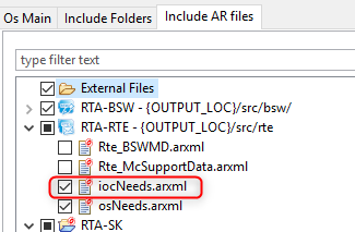
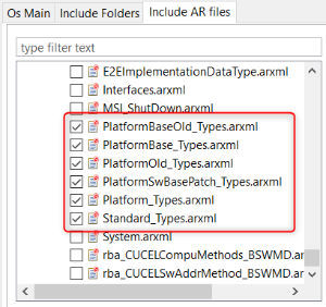
The following files are also required for a successful generation.

Step 7.2 Update Target Specific Configuration
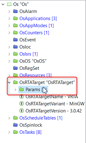
In the ECU Configurator, double click the Rte Os Os container.

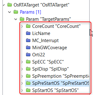
Select the OsRTATARGET container, and then the params subcontainer.
Right-click on the container and select Create Param.

This will generate a new param container with a default name of Params_0, which we will rename to TargetParams.
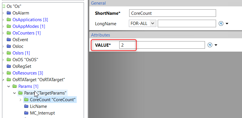
All of these target specific parameters will have been created with the default value of 0. We now need to go through each and set a value. Start by selecting the CoreCount container. This represents how many cores we have configured so we want to set this to the value 2 as follows:
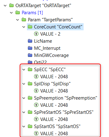
All of the other target specific parameters we created are stack values for starting the Os, dispatching extended tasks and more.
For the Virtual target, we set all of these to a value of 2048, but on a hardware target these values would need analysing for the specific system/memory requirements.
Following setting each of these stack values to 2048 you should see the following:
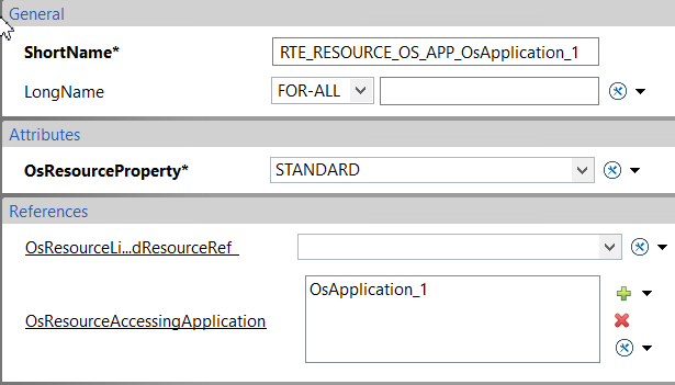
Step 7.3 Create Os Resources
We now need to create 3 new Os Resources, one for each Os Application that we created in Step 3.

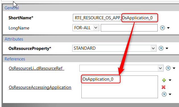
Right click on the Os container and click Create Child → OsResource
For each Resource, you need to add a reference to the appropriate accessing Os Application, as shown in the following examples.

Step 7.4 Referencing RTE Created Os Objects
When we generated the RTE in Step 6, the osNeeds.arxml file was automatically generated. This file contains Os items required by the RTE.
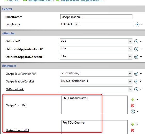
In our example project, the RTE has generated a counter (Rte_TOutCounter) and an alarm (Rte_TimeoutAlarm1) for the triggering of the OsTask_ASW_Core1 task, which contains the RE_MainCore1 runnable of our new Core1SWC. This extended task can wait on Client Server communication from the Nvm Service.
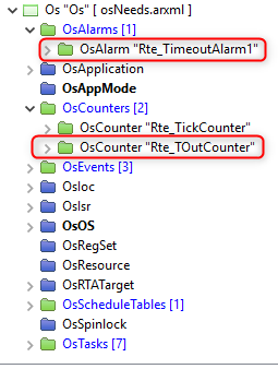
These elements need to be mapped in the OS configuration inside the OsApplication 1 on Core 1.
7. Conclusions
Following this example workflow you now have a basic multicore environment, which is comprised of two cores (Core0 and Core1) and two SWCs (MasterSWC running on Core0 and Core1SWC running on Core1). The multicore functionality is demonstrated with a simple communication between the two SWCs, with MasterSWC sending a Test Code to Core1SWC, and Core1SWC responding to MasterSWC with a Test Result.