PDF version of this AN - SWC_Calibration.pdf
Introduction
This application note describes how to configure an existing ISOLAR project using ISOLAR A/B 9.2.0 to add the calibration of some parameters specific to a SWC. The document contains an explanation step by step of the workflow to follow to obtain a working project. A sample project is provided along with this document configured as shown in this application note. As starting project the RTA-SK_VRTA_GCC_Standard_9.2.0_R1.zip is used, all the steps listed below can be performed on this project to reproduce the sample project.
Definitions and Abbreviations -
BSW: AUTOSAR Basic Software, Hardware independent service layer.
RTE: AUTOSAR Real Time Environment.
OS: AUTOSAR Operating System.
SWC: Software Component.
AR: AUTOSAR
AN: Application Note
ROM: Read Only Memory
RAM: Random Access Memory
API: Application Programming Interface
Toolchain
It is assumed you are using the RTA-CAR 9.2.0 toolchain:
RTA-CAR 9.2.0 toolchain | |
|---|---|
| ISOLAR-AB | v 9.2.0 |
| RTA-RTE | v 7.5.0 |
| RTA-BSW | v 6.1.2 |
RTA-OS | v 6.2.0 |
| ISOLAR-EVE | v 3.4.0 |
Prerequisites
To complete and fully implement the steps in this
It is assumed that the Reader has good knowledge of AUTOSAR Methodology and Architecture, as well a good understanding of the Memory Stack specified by AUTOSAR.
AR Calibration overview
AUTOSAR groups calibrations into three main categories based on the accesseability of the parameters. Calibration parameters can be:
- SWC instance specific
- SWCType specific but shared among all the SWC instances of the same type
- Global: shared among different SWC types
Thus, there are three AR artifacts corresponding to these three categories:
- SWC specific parameters are implemented in AR using a particular type of ParameterDataPrototype named perInstanceParameters; these are defined for each SWC instance
- parameters shared among SWC instances of the same SWC type are implemented with two other ParameterDataPrototype: constant memories and shared parameters
- global parameters are implemented using SWC R ports and a ParameterSWC offering all the PPorts to the SWCs
SWC specific calibration
This AN focuses on the first category only. Calibration of SWC specific parameters involves two main steps:
- configuration of SWC description
- RTE generation based on proper options
Four different methods to calibrate the SWC specific parameters will be explained. Most of the configuration is common to all of them; while the RTE generation differs for each method.
"Workflow description" chapter describes the configuration steps while the chapters after analyse the output code of each method.
The four calibration methods used are:
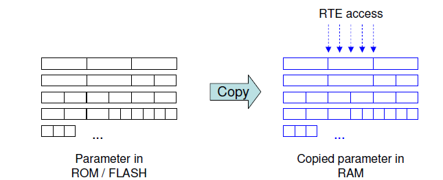
- Initialized RAM: all SWC parameters are stored in a Flash Memory Section; during the ECU startup all these parameters are copied into a user defined RAM Memory section. The latter will be used at runtime from the SWC's runnables to read the parameters values.
- Single Pointered: a table of pointers to Flash Memory Addresses is created in a user defined RAM Memory section; at runtime the SWC makes use of the pointers to read the parameters values.
- Double Pointered: a table of pointers to Flash Memory Addresses is created in a user defined section of Flash Memory while the RAM Memory will have a BaseAddressReference which is a pointer to the starting address of the Flash Memory Table; theBaseAddress and eventually an offset is used to access the parameters values.
- Single Pointered Variant: this method is another implementation of the Single Pointered one; it is realized using an RTA-RTE extension of AR which allows to define several parameters memory sections for each SWC.
Sample project overview
In the example used for this AN we used two parameters of two different BaseType:
- Param_1 --> uint8
- Param_2 --> uint16
These parameters will be set to an initial value in Flash memory of:
- Param_1 = 5
- Param_2 = 2000
Workflow description
SwAddrMethod definition
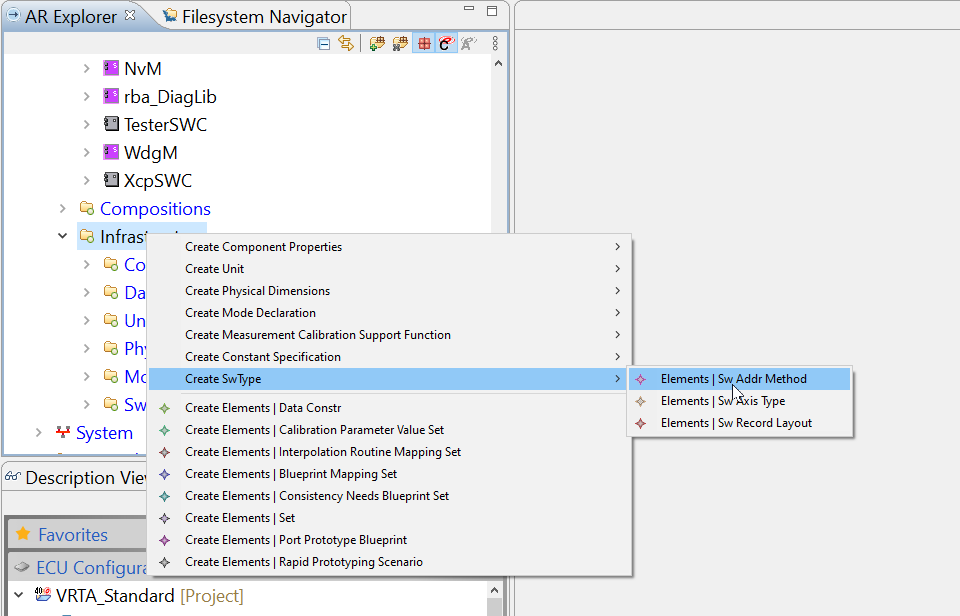
Since the parameter will be placed in a defined memory section we need to create a new SwAddrMethod which will be used to link each parameters to a defined RAM memory section. In the AR explorer menu go to "Infrastructure", right click and select New SwType --> Elements | SwAddrMethod:
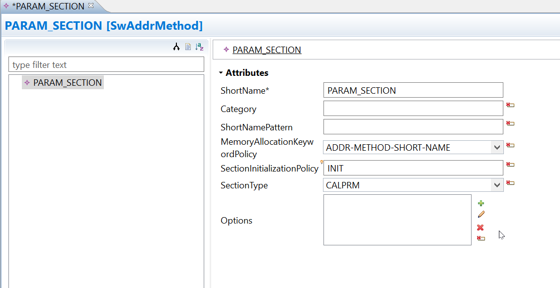
Open the created item and set the properties as desired; for Section Type choose "CALPRM" since the data to store are calibration parameters.
PerInstanceParameter creation
We will add these parameters to the master SWC so that later we can test reading these parameters using CAN, however, you may want to add them to a XCP if your want to use them with INCA.
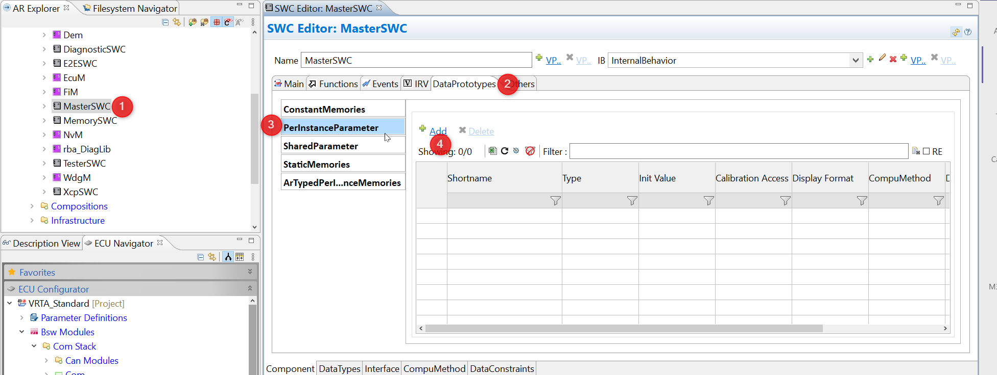
Open the existing SWC "Master_SWC" and switch to tab DataProtoypes; here go to Tab PerInstanceParameter and then click Add;
Then begin filling the fields in as required. Here is the example steps to create our "param1" with a uint8 type and inital value of 5:
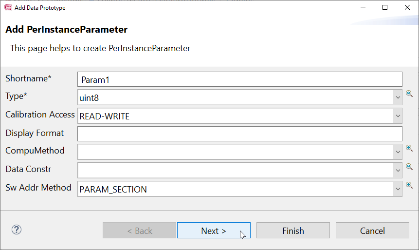
Then click Next to configure a NumericalInitValue with no constants for init value and give it the value of 5.
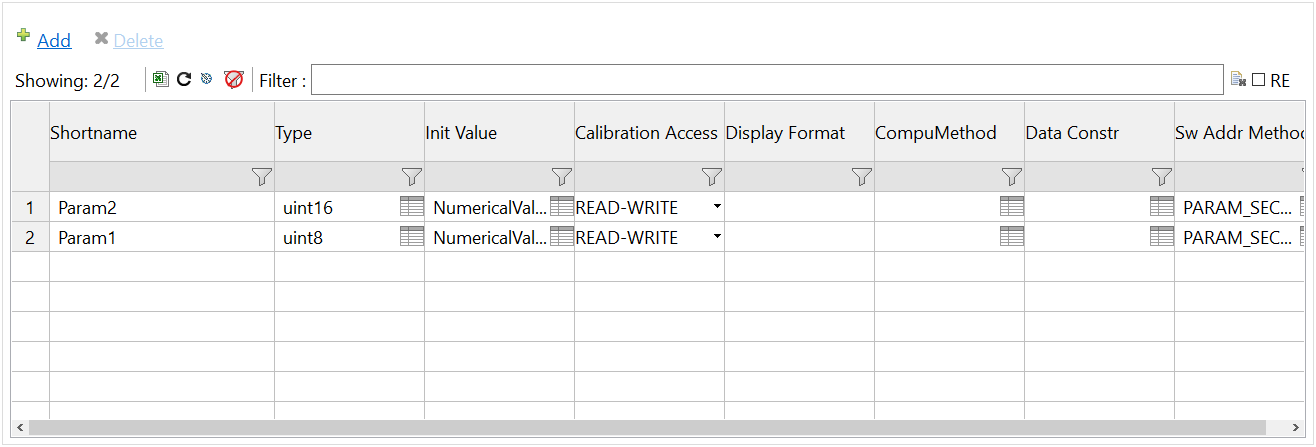
You should repeat this step to produce param2 with a value of 2000 and a type of unit16, then you should have 2 params configured which look like this.
Runnable configuration
Each runnable defined in the SWC must be configured to have access to the parameter; to do this, open the SWC with the Component Editor, go to Functions Tab, select the desired runnable and on the right open the ParameterAccessPoints Tab to add the access point to the parameters:
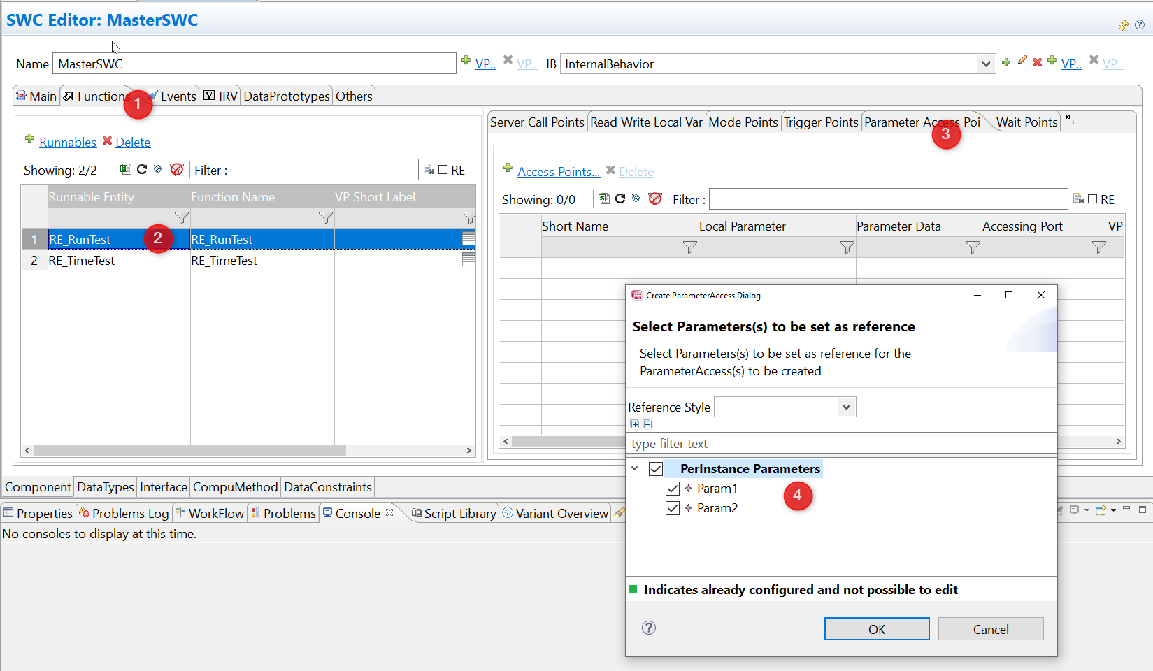
If you can't see the tab called "Parameter Access Points" in the right hand table you may need to click on the double right arrows to show more more tabs.
Important notes
If a parameter is not accessed by any runnable the RTA-RTE optimization mechanism does not create any macro to read the parameter from the SWC.
RTE generation
This final step is dependant on the calibration method chosen; the RTE must be generated using the additional command "--calibration-method" with the value set to the desired method. The four options supported by the RTA RTE are:
- “initializedRam” – RTA-RTE generates a RAM copy of all parameters and an initializing ROM block. Generated RTE APIs access the RAM copy.
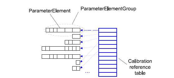
- “singlePointered” – RTA-RTE generates a reference table (in RAM) that locates calibration data. The calibration values returned by individual generated RTE APIs can be modified by changing pointers in the reference table to point to alternate values in either RAM or ROM.
- “singlePointered2” – RTA-RTE generates individual reference pointers (in RAM) that locate calibration data. The calibration values returned by individual generated RTE APIs can be modified by changing those reference pointers. This is a non-AUTOSARextension.
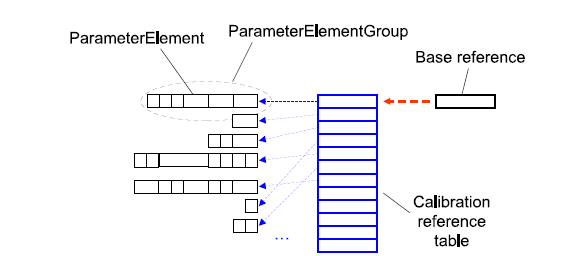
- “doublePointered” – RTA-RTE generates a reference table (in ROM) and a reference base (in RAM) that points to the table. The calibration values returned by all generated RTE APIs can be modified by changing the base pointer to reference a different table.
As default the configuration for the RTE module will include a parameter RteCalibrationSupport which as has a default value of NONE and a lower multiplicity of NONE. This means that if you use any of the above commandline options you will get a warning that is recognises 2 different global definitions for calibration method. This is expected and ok as the commandline option takes precedence over the option in RteCalibrationSupport.
Initialized RAM Method
Generating the RTE for this method (additional command to RTE generation: "--calibration-method=INITIALIZED_RAM") will give as output an Rte.c file where the following items should be defined:
- RAM memory section for all the parameters
- Flash memory section with initial values of parameters
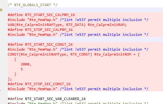
- During Rte startup phase, the copy from Flash (ROM) memory to RAM memory is implemented in
Rte_Lib.c:

Important notes on this method
When using calibration method “Init-RAM”, RTA-RTE creates a single combined RAM block containing space for all the calibration parameters and a single combined ROM block with the initializer for every calibration parameter. Both blocks use the structure type Rte_CalprmInitRAMType. The RAM block is instantiated as a variable of that type called Rte_CalprmInitRAM and the ROM block is instantiated as a constant of that type called Rte_CalprmInitROM. Within the blocks the parameters are grouped together by SWC and SwAddrMethod names. This scheme allows a single copy operation to perform the initialization of all parameters at once.
**NB: ** this method is advisable when a low number of parameters have to be calibrated, besides startup copy from Flash to RAM time must be considered to enable fulfilling of ECU startup timing requirements.
Single Pointered method
To use this method, RTE must be generated using the additional command "--calibration-method SINGLE_POINTERED". The output code will define a specific memory section in Flash named using the SwAddrMethod associated to DatPrototypes where calibration values will be stored:
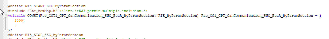
In RAM a reference table is created with a variable storing the Flash address of the parameters memory section start:
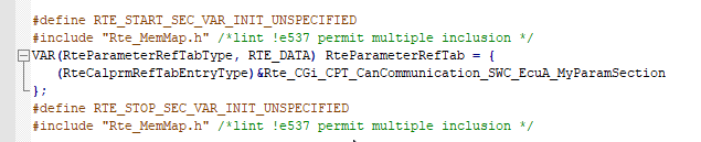
**NB: ** in case more SwAddrMethods have been associated to parameters of the same SWC, more parameter groups (read Flash memory sections) will be created; in that case the RAM reference table will store the address of the start of each Flash memory section defined:
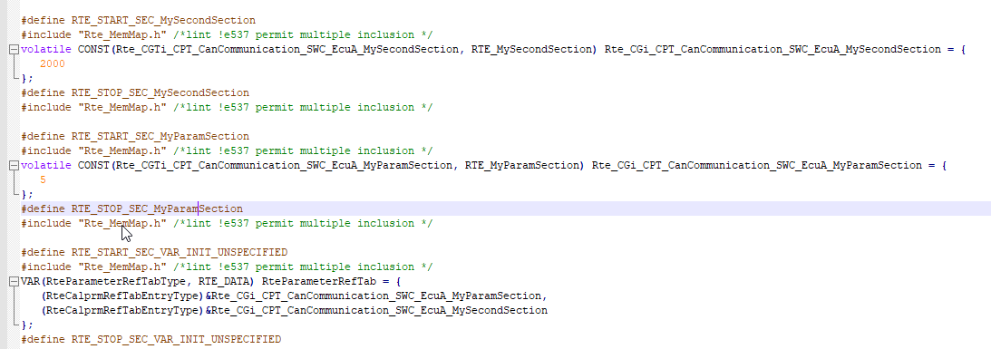
This method allows to define memory sections to create groups of parameters using one SwAddrMethod for each group.
Single Pointered 2 method
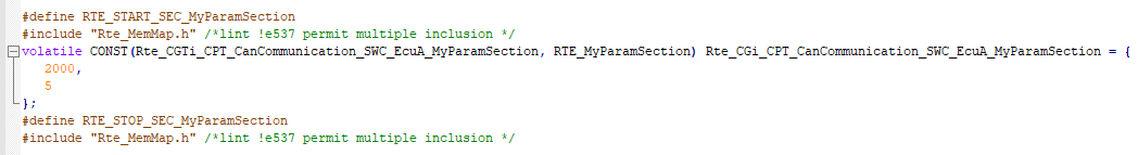
This method implements the AR Single Pointered method adding the freedom to use only one SwAddrMethod for all the parameters but keeping the differentiation in terms of memory sections defining one section for each SWC instance. This method is an extension of AR supported by RTA-RTE. The output code for this example would be the following:
In flash, the memory section name define contains the name of the SWC, the ECU Instance and the name of the SwAddrMethod (if defined, otherwise a "NULLSWADDR_16" extension is added):
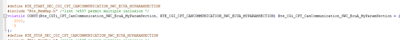
In RAM the table is replaced by a variable for each parameter group defined storing the starting Flash address of the corresponding memory section:

Below an example of two parameters groups defined:
Double Pointered method
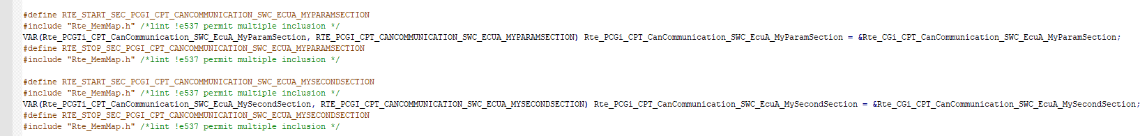
The additional command to use this method is "DOUBLE_POINTERED". The output code is a memory section for each SwAddrMethod in Flash storing the calibration values:
Besides these, another Flash memory section defines a reference table to the previous sections starting addresses:
In RAM only one variable is used to store the address of the reference table in Flash.

**NB: ** this method's pro is a very low use of RAM (only one address).
Reading parameters from SWC
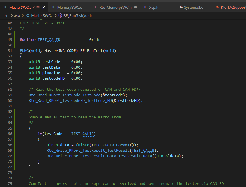
Parameters can be accessed by SWC using the RTE defined macros:
/* Inline calprm optimization; Rte_CData_Param1 to direct access */
#define Rte_CData_Param1() ( (volatile CONST(uint8, _CALPRM)) Rte_CalprmInitRAM.CGi_CPT_MasterSWC_PARAM_SECTION.Param1 )
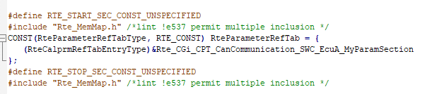
Implementation of these macros depends on the calibration method used; for example for single pointered method a macro would be as following:
#define Rte_CData_Param_1( self ) ( (volatile CONST(uint8, RTE_MyParamSection)) (((volatile P2CONST(Rte_CGTi_CPT_CanCommunication_SWC_EcuA_MyParamSection, AUTOMATIC, RTE_MyParamSection))RteParameterRefTab[((VAR(uint16, AUTOMATIC))RTE_CGI_CPT_CANCOMMUNICATION_SWC_ECUA_MYPARAMSECTION)])->Param_1) )
In this case the macro takes for the reference table in RAM the address of Flash memory and use it to access to parameter value.
For example in the ASW I have modified the MasterSWC function RE_RunTest to read the value of the parameter and send it over a CAN signal.
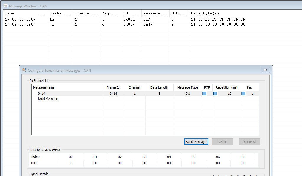
And here in Busmaster you can see it returning the value of 5 from Param1 successfully.
Next steps after adding calibration parameters - calibration of parameters using XCP through INCA
After implementing the parameters you may wish to calibrate them. One recommended method to do this is to configure the XCP module and use INCA to be able to read and write to the variables stored in RAM. To do this please follow the application note "How to configure XCP"